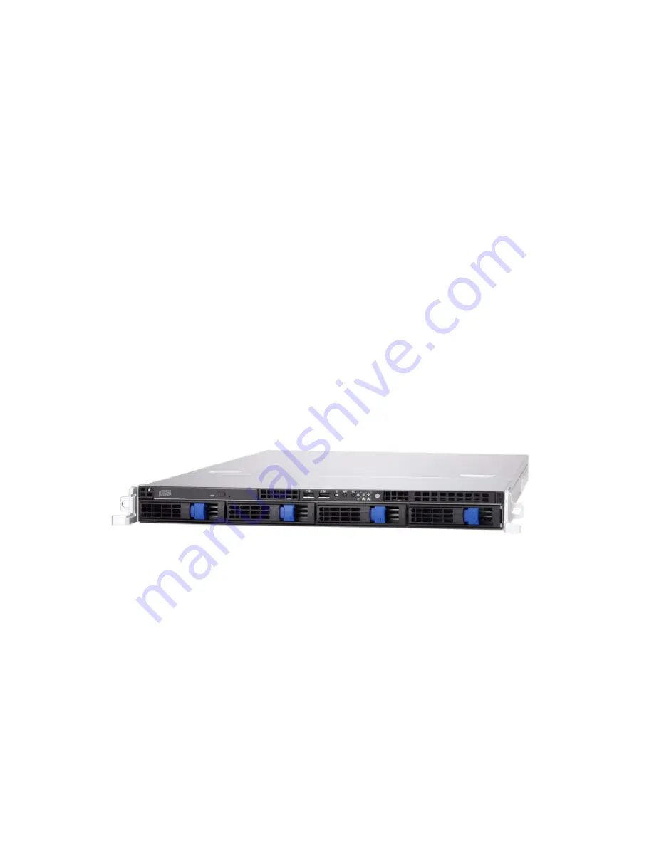
Tank™
GT24
B5383
Service Engineer’s Manual
Page 1: ...Tank GT24 B5383 Service Engineer s Manual...
Page 2: ......
Page 3: ...Work Area 16 2 0 3 Tools 16 2 0 4 Precautions 17 2 1 Rack Mounting 18 2 1 1 Installing the Server in a Rack 18 2 2 Installing Motherboard Components 23 2 2 1 Removing the Chassis Cover 23 2 2 2 Insta...
Page 4: ...oard 47 3 7 1 M1012 Adapter Board Features for B5383 48 3 7 2 M1012 Adapter Board Connector Pin Definition 49 3 8 Replacing the SAS SATA M1208 Backplane 53 3 8 1 SAS SATA Backplane M1208 Features 55 3...
Page 5: ...uct descriptions and or specifications at any time without notice In no event will TYAN be held liable for any direct or indirect incidental or consequential damage loss of use loss of data or other m...
Page 6: ...to an outlet on a circuit different from that of the receiver Consult the dealer on an experienced radio television technician for help Notice for Canada This apparatus complies with the Class B limit...
Page 7: ...xternal components gives a table of key components and provides block diagrams of the system Chapter2 Covers procedures on installing the CPU memory modules hard drives and Slim FDD optional Chapter3...
Page 8: ...is pin If you outlet does not support this kind of plug contact your electrician to replace your obsolete outlet Do not place anything on the power cord Place the power cord where it will not be in th...
Page 9: ...o 64GB DDR2 533 667 FBDIMM The Tank GT24 B5383 not only empowers your company in today s demanding IT environment but also offers a smooth path for future application usage TYAN is also proud to deliv...
Page 10: ...1 2 Product Models Model HDD Bay HDD Supported Backplane Motherboard B5383G24W4H Removable 4 HDDs SAS 4 port SAS SATAII S5383WG4NR 2 Chapter 1 Product Overview...
Page 11: ...el Features I O 2 USB2 0 ports LED indicators Power LED 2 LAN LEDs for 2 port LAN from Intel Gilgal 82563EB HDD Active LEDs only for HDD connected to SATA connector ID LED Warning LED Switches Power R...
Page 12: ...gement TSM Optional TYAN SMDC kit IPMI 2 0 compliant System Cooling 4 40 40 56mm 14500rpm system fans 1 40 40 28mm 14000rpm system fan 2 passive CPU heatsinks Power Supply PS 12V 1U 650W 600W with PFC...
Page 13: ...ents are present and undamaged The product should arrive packaged as illustrated below 1 4 1 Box Contents Component Description Industry standard 1U chassis 4 hot swap HDD bays Tyan S5383 system board...
Page 14: ...ent Description Air Duct 4 System fans 40mm x 40mm x 56mm 1 System fans 40mm x 40mm x 28mm M1012 Adapter Board M1208 SAS SATA Backplane EPS 1U 650W with PFC EPS 1U 600W with PFC 6 Chapter 1 Product Ov...
Page 15: ...rvice http www tyan com The Web site also provides information on other TYAN products plus FAQs compatibility lists BIOS settings and more 1 x Tyan Barebone Drive CD Barebone Manual Motherboard Manual...
Page 16: ...Rail Kit Mounting Bracket x 4 Screw Kit Sliding Rail x 2 Sliding Brackets Front L Bracket x 2 Rear L Bracket x 2 FDD Kit FDD Backplane Cable FDD Cable FDD Rails Screws 8 Chapter 1 Product Overview...
Page 17: ...duct 1 5 2 System Rear View Power Supply Socket PS 2 Mouse Keyboard Ports LAN2 Port LAN3 Port LAN4 Port LAN1 Port USB Ports Serial Port VGA Port DVD ROM Drive Hard Drive Bay x 4 USB Ports Power Switch...
Page 18: ...OFF Fan failure Over Temperature Voltage failure Normal Hot Swappable HDD Tray Power LED Green ON OFF HDD connected HDD disconnected Hot Swappable SATA HDD Access LED Amber Blinking OFF HDD access ac...
Page 19: ...er Blinking 3 Blinking 2 Blinking 1 OFF Gigabit mode 100M mode 10M mode No LAN link RJ45 NIC2 Linkage Left Side Green ON OFF LAN Linked LAN Accessing No LAN link RJ45 NIC2 Mode Right Side Amber Amber...
Page 20: ...Slots 7 Four SATA SAS HDD Bays 2 Power Supply 8 Slim DVD ROM 3 CPU Air Duct 9 DVD Power Cable 4 System Fans 10 DVD ROM Cable 5 SAS SATA Backplane M1208 11 M1012 Adapter Card 6 LED Control Board Cable...
Page 21: ...ble on S5383WG2NR model is reserved feature of S5383 This diagram is representative of the latest board revision available at the time of publishing The board you receive may not look exactly like the...
Page 22: ...3_Pin x 2 J79 SMDC CON25 x 2_M3291 J80 IPMB Pin Header J88 COM PORT Pin Header JP6 Optional LAN4 LED Pin Header JP10 Clear CMOS Jumper JP3 JP4 Optional LAN3 LAN4 Enable Disable Jumper JP7 JP8 LAN1 LA...
Page 23: ...1 5 6 System Block Diagram Chapter 1 Product Overview 15...
Page 24: ...rs prevents them from becoming lost Adequate lighting and proper tools can prevent you from accidentally damaging the internal components 2 0 3 Tools The following procedures require only a few tools...
Page 25: ...ce z Avoid touching motherboard components IC chips connectors memory modules and leads z The motherboard is pre installed in the system When removing the motherboard always place it on a grounded ant...
Page 26: ...ese instructions to mount the GT24 B5383 into an industry standard 19 rack NOTE Before mounting the Tank GT24 B5383 in a rack ensure that all internal components have been installed and that the unit...
Page 27: ...from the supplied screws kit 2 Draw out the inner rails from rail assembly Install inner rails to left and right sides of chassis using 2 M4 5L D screws for each side 2 1 1 2 Installing the Outer Rail...
Page 28: ...e 40mm for GT24 B5383 on the front bracket Secure the front bracket to outer rail with 2 M4 4L C screws 4 Reserve the distance same as in Step 2 on rear bracket Secure the rear bracket to outer rail w...
Page 29: ...2 brackets and 4 M4 8L E screws for each side A Secure the mounting brackets from inside not outside of the rack B A Mounting Bracket B 2 1 1 3 Rackmounting the Server 6 Draw out the middle rail to t...
Page 30: ...s the latch key A Then push the whole system into the rack B A B 9 Secure the mounting ears of chassis to the rack with 2 M4 15L F screws NOTE To avoid injury it is strongly recommended that two peopl...
Page 31: ...including CPU memory modules and hard drive 2 2 1 Removing the Chassis Cover Follow these instructions to remove the Tank GT24 B5383 chassis cover 1 Thumb the screw on the back side as shown in the sm...
Page 32: ...nk Follow these instructions on install CPU0 CPU1 and the CPU heatsinks 1 Remove the screws securing the pre installed air duct 2 Remove the air duct and locate the CPU sockets 3 Take off the CPU prot...
Page 33: ...the CPU lever up to unlock the CPU socket 5 Open the socket in the direction as shown in the diagram 6 Place the CPU in the CPU socket ensuring that pin 1 is located as shown below Chapter 2 Setting...
Page 34: ...et lever down to secure the CPU 8 Place the heatsink on top of the CPU and secure into place as shown 9 Repeat Step 3 to Step 8 to install a second CPU as you need 10 Place and secure the air duct bac...
Page 35: ...therboard 1 Locate the memory slots on the motherboard 2 Press the memory slot locking levers in the direction of the arrows as shown in the following illustration 3 Align the memory module with the s...
Page 36: ...4 Insert the memory module into the slot as shown When inserted properly the memory slot locking levers lock automatically onto the indentations at the ends of the module 28 Chapter 2 Setting Up...
Page 37: ...ry Slot Quantity of memory installed 1 2 4 6 8 16 DIMM 1 X X X X X X X X X DIMM 2 X X X X X X DIMM 3 X X X DIMM 4 X X DIMM 5 X X X X X X X X DIMM 6 X X X X X X DIMM 7 X X X DIMM 8 X X DIMM 9 X X X X D...
Page 38: ...hard drives Follow these instructions to install an external SAS SATA hard drive 1 Press the locking lever latch in the direction of arrow A and then pull the locking lever open B A B 2 Slide the driv...
Page 39: ...to secure the HDD 5 Reinsert the drive tray into the chassis A ensuring that the drive tray is completely inserted into the chassis B A B 6 Press the locking lever to secure the hard drive tray Chapt...
Page 40: ...wo FDD rails FCC cable and screws from the FDD kit Secure the two rails to the FDD using four screws FDD Rails FDD FCC Cables Screws 2 Connect the FCC cable to the FDD 3 Use a screw driver to pull ope...
Page 41: ...Connect the wrinkle side to the connector on the FDD backplane Refer to the picture below for the correct direction Then connect the power cable of FDD to the connector on the FDD backplane 6 Connect...
Page 42: ...small components in separate containers prevents them from becoming lost Adequate lighting and proper tools can prevent you from accidentally damaging the internal components 3 1 2 Tools The following...
Page 43: ...ouching motherboard components IC chips connectors memory modules and leads z The motherboard is pre installed in the system When removing the motherboard always place it on a grounded anti static sur...
Page 44: ...3 2 Disassembly Flowchart The following flowchart outlines the disassembly procedure 36 Chapter 3 Replacing Pre Installed Components...
Page 45: ...cover Follow these instructions to remove the cover of the Tank GT24 B5383 chassis cover 1 Thumb the screw on the back side as shown in the small diagram Then slide the chassis cover in the direction...
Page 46: ...es Before replacing the motherboard or certain components remove cables connected to the motherboard Follow these instructions to remove all motherboard cabling 1 Disconnect Power Cables 2 Disconnect...
Page 47: ...ront Panel Header cable Fan connector cable and Front Panel Header cable Intrusion header cable Front Panel Header cable Fan Connector cable Front Panel Header cable Cable Location Diagram Chapter 3 R...
Page 48: ...ese instructions to remove the motherboard from the chassis when all add on components have been removed 1 Remove eight screws securing the motherboard to the chassis 2 Remove the motherboard 40 Chapt...
Page 49: ...ace the DVD ROM 1 Remove power and data cables from the slim DVD ROM adapter 2 Press the tab in the directions as shown to release the DVD ROM drive 3 Free the DVD ROM drive from the drive bay after p...
Page 50: ...drive to the bracket 5 Replace the DVD ROM drive 6 Secure DVD ROM to the bracket using two screws Then replace the unit into the drive bay and connect the DVD ROM power and data cables as in step1 42...
Page 51: ...ollow these instructions to replace the LED control board 1 Remove the two screws securing the LED control board unit to the chassis 2 Lift the LED control board unit free from the chassis Chapter 3 R...
Page 52: ...r 4 Remove three screws securing LED control board to the bracket 5 Lift the LED control board free from the chassis After replacement insert the unit into the chassis following the above procedures i...
Page 53: ...3 6 1 M1003 LED Control Board Features Chapter 3 Replacing Pre Installed Components 45...
Page 54: ...ront Panel Connector 1 HDLED 2 HDLED 3 RESET 4 RESET 5 PW_LED 6 PW_LED 7 WLED 8 WLED 9 OCJ_SMBDAT 10 ICH_SMBCLK 11 EXT_INT 12 VOLTAGE5 13 V5SB 14 INTRU 15 PWR_SW 16 PWR_SW 17 LAN1_LED 18 LAN1_LED 19 L...
Page 55: ...to the adapter board including SAS SATA cables fan cables DVD ROM power cable front panel control board cable TYFP cables and power cables Refer to the pictures below for locations 2 Remove six screws...
Page 56: ...or FDD2 Slim FDD Connector J15 LCM Connector PW2 Power Connector JP1 Fan Input Select Connector J3 LAN ID LED Connector FDD1 Standard Floppy Connector J1 Front Panel Connec tor JP2 Fan Minimum Voltage...
Page 57: ...ion Pin Definition 1 HDLED 2 HDLED 3 RESET 4 RESET 5 PW_LED 6 PW_LED 7 WLED 8 WLED 9 ICH_SMBDAT 10 ICH_SMBCLK 11 EXT_INT 12 VOLTAGE5 13 V5SB 14 INTRU 15 PWR_SW 16 PWR_SW 17 LAN1_LED 18 LAN1_LED 19 LAN...
Page 58: ...Connector Pin Definition 1 GND 2 NC 3 FAN1_TACH 4 PWM1 Default J7 Fan TACH PWM Connector Pin Definition 1 GND 2 NC 3 FAN7_TACH 4 PWM1 Default J8 PWM Connector Pin Definition 1 GND 2 PMW2 3 FAN1_TACH...
Page 59: ...ACH 17 GND 18 FAN9_TACH 19 GND 20 FAN10_TACH 21 KEY PIN 22 PWM J6 Fan Connector Pin Definition 1 FAN1_12VPWM 2 FAN1_TACH 3 GND 4 GND 5 FAN2_TACH 6 FAN2_12VPWM J10 Fan Connector Pin Definition 1 FAN3_1...
Page 60: ...ACH 6 FAN10_12VPWM J15 J16 LCM Connectors Definition Pin Pin Definition LCM_ 5V 1 2 LCM_SIN Key 3 4 GND LCM_ 5VSB 5 6 LCM_SOUT JP1 Fan Input Select Connector Pin1 Pin2 Close Fan PWM signal from J8 Pin...
Page 61: ...acing SAS SATA backplane are the same 1 Remove the three screws securing the adapter board to the chassis 2 Grab the two labels to lift the adapter board 3 Remove the ten screws that secure the bracke...
Page 62: ...4 Release the adapter board free from the bracket 5 Replace the unit to the chassis following the above procedures in reverse 54 Chapter 3 Replacing Pre Installed Components...
Page 63: ...SAS SATA Backplane M1208 Features U4 SAS SATA4 Connector U3 SAS SATA3 Connector U2 SAS SATA2 Connector U1 SAS SATA 1 Connector HDD Access LED HDD Power LED Chapter 3 Replacing Pre Installed Component...
Page 64: ...PW1 Power Connector J4 SAS SATA 4 J3 SAS SATA 3 J2 SAS SATA 2 J1 SAS SATA 1 PW2 Power Connector Connector Connector Connector Connector 56 Chapter 3 Replacing Pre Installed Components...
Page 65: ...instructions to replace the 650W power supply 1 Disconnect power cables as shown in the diagram 2 Remove the two screws that secure the power supply to the chassis 3 Remove the screw that secures the...
Page 66: ...power supply free from the chassis 5 Place a new power supply in position in the chassis and secure in place with the three screws Then reconnect the power cables 58 Chapter 3 Replacing Pre Installed...
Page 67: ...ecure the power supply to the chassis 3 Remove the two screws that secure the power supply to the chassis as shown in diagram A And lift the power supply free from the chassis as shown in diagram B 4...
Page 68: ...e Health Information menu See the following for the differences S5383 Advanced Hardware Health Information PhoenixBIOS Setup Utility Main Advanced Power Boot Exit Hardware Monitor Item Specific Help X...
Page 69: ...ardware Monitor Item Specific Help XVoltage Monitoring SYS_FAN1 SYS_FAN2 SYS_FAN3 SYS_FAN4 SYS_FAN5 SYS_FAN6 SYS_FAN7 SYS_FAN8 SYS_FAN9 CPU0 Temp CPU1 Temp Auto Fan Control Enabled F1 Help Select Item...
Page 70: ...erences S5383 B5383 Auto Fan Control Disabled Enabled Hardware Monitor Fan CPU0 Fan CPU1 Fan SYS_FAN1 SYS_FAN2 SYS_FAN3 SYS_FAN4 SYS_FAN1 SYS_FAN2 SYS_FAN3 SYS_FAN4 SYS_FAN5 SYS_FAN6 SYS_FAN7 SYS_FAN8...
Page 71: ...d Connect to Motherboard SAS SATA 1 J5 SAS 1 SAS SATA 2 J3 SAS 2 SAS SATA 3 J2 SAS 3 SAS SATA 4 J1 SAS 4 Fan Cables Table 2 System Fan to M1012 Adapter Board System Fan Connect to M1012 Fan 1 J6 Fan C...
Page 72: ...8 pin power cable PWR1 8 pin connector P3 4 pin power cable PWR2 4 pin connector P1 24 pin power cable PWR3 24 pin connector Table 5 Power Supply to M1012 Adapter Board Power Supply Connect to M1012...
Page 73: ...03 J1 USB Connector Motherboard J11 M1003 J2 Connector M1012 J2 Connector Table 9 DVD ROM Related Cables Motherboard IDE Connector DVD ROM Backplane M1012 J19 Power Connector DVD ROM Backplane Table 1...
Page 74: ...ormation on installing SMDC card You may refer to the following for installing M3291 into HDD tray Installing SMDC Screws List A Flat 6 32 x4 x16 B B type 6 32 x4 G 13 5mm stand off x1 1 Secure a remo...
Page 75: ...ion of SMDC connector on motherboard for choosing a HDD tray b Secure SMDC card to the HDD tray 4 a Insert the cable into the rear of HDD tray b Connect the cable to M3291 c Insert and secure HDD tray...
Page 76: ...1000 LCM Module Packing List 1 M1000 LCM Module x 1 2 CCBL 0602 cable x 1 3 CCBL 0600 cable x 2 1 Hardware Setup Step 2 Slide the HDD tray out Use a screw driver to pull the FDD tray out Step 1 Press...
Page 77: ...3 3 Connect the other end of the CCBL 0600 cable to J3 on the LCM module Step 3 4 Use the second CCBL 0600 cable to connect the 2x3 pin LCM header on the mainboard and J16 on the M1010 M1012 adapter...
Page 78: ...e power cord P5 Step 4 4 Locate the COM2 header on the main board The location of COM2 may vary from model to model Use the CCBL 0602 LCM cable to connect COM2 and J16 on M1010 M1012 Step 4 3 the othe...
Page 79: ...e the installation Technical Support If a problem arises with your sys tem you should rst turn to your dealer for direct support How ever if the option is not available for you please feel free to con...
Page 80: ...iver Installation for Linux Step 1 Install M1000 driver for Linux TCLCD 0 2 tar gz or the latest version 2 Software Setup Here shows the LCD Front Panel and its four control buttons 3 1 Key De nition...
Page 81: ...odel Name Transport GT20 MODEL B3870 3 Peripheral Device PCI Initialize Resource Allocate 4 CPU Info RAM Info CPU 2800 MHz Memory 2048 MB 5 FAN Info All System FANs Are Working Dete MODEL name will ch...
Page 82: ...ress 10 59 5 107 Net Mask 255 255 255 0 Gateway 10 59 5 254 1 2 NIC1 DHCP IP Address 10 59 5 108 Net Mask 255 255 255 0 Gateway 10 59 5 254 System Nics Performance Power Ctl System Sensors Windows Mod...
Page 83: ...0 Bps NIC1 Flow Speed 0 Bps 3 System Sensors 3 1 Fan Chassis Fan2 9300 RPM Chassis Fan3 9420 RPM Chassis Fan4 9360 RPM Chassis Fan5 9360 RPM 3 2 Voltage DIMM Volt 2 60 V VCCP 1 35 V System Volt 3 3 3...
Page 84: ...N s website www tyan com provides easy to access resources such as in depth Linux Online Support sections with downloadable Linux drivers and comprehensive compatibility reports for chassis memory and...
Page 85: ...t cover damages incurred during shipping or failure due to the alteration misuse abuse or improper maintenance of products NOTE A receipt or copy of your invoice marked with the date of purchase is re...