background image


http://www.tyan.com 

23


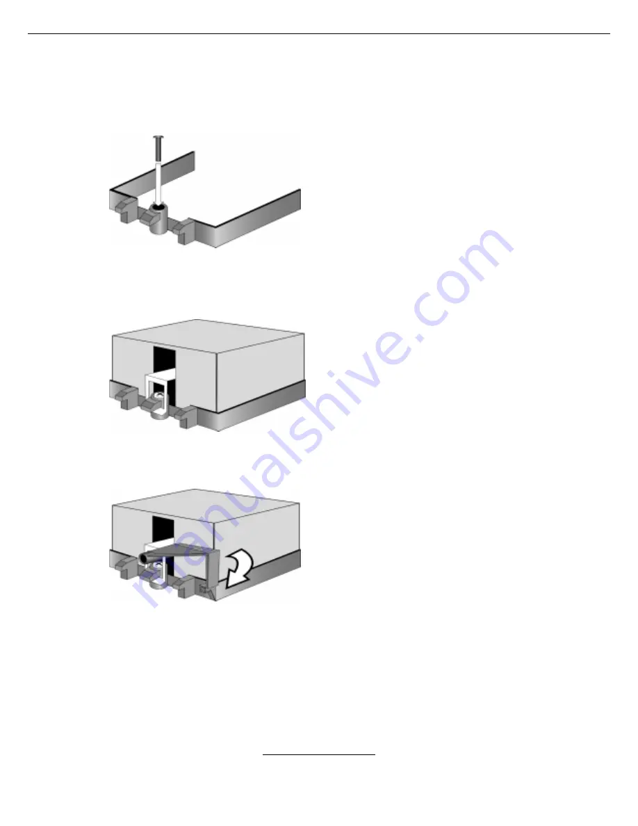
2.7 -  Heatsink Installation Procedures 


Type A: CAM LEVER (TYPE) INSTALLATION 


1.  After placing backplate and 
interface material under motherboard 
place heatsink retention frame on top 
of motherboard. Align plastic retention 
bracket screw holes with CPU back-
plate standoffs. 
Tighten screws to secure plastic 
retention bracket. Repeat for the other 
side. 

DO NOT OVER TIGHTEN. 


2. After tightening screws secure 
metal clip to plastic retention bracket 
center tab. Repeat for the other side 
of heatsink. 


3. After securing metal clip to plastic 
retention bracket center tab, push 
down on plastic clip to lock plastic clip 
to side tab.  


Summary of Contents for S2892

Page 1: ...ademark of SuSE AG Linux is a trademark of Linus Torvalds IBM PC AT and PS 2 are trademarks of IBM Corporation Winbond is a trademark of Winbond Electronics Corporation Notice Information contained in...

Page 2: ...in Chassis Page 25 2 9 Installing the Memory Page 26 2 10 Attaching Drive Cables Page 29 2 11 Installing Add In Cards Page 31 2 12 Connecting External Devices Page 32 2 13 Installing the Power Supply...

Page 3: ...ocessors Two uPGA 940 pin ZIF sockets Supports one or two AMD OpteronTM processors Integrated 128 bit Dual Channel DDR memory controller Chipset Nvidia nForce pro2200 AMD 8131 PCI X Tunnel Winbond W83...

Page 4: ...r Temperature voltage and fan monitoring Integrated Enhanced IDE Controller Two IDE dual drive ports for up to four EIDE devices Supports for UDMA 133 100 66 33 IDE drives and ATAPI devices BIOS Phoen...

Page 5: ...d USB 2 0 two with one RJ45 connectors Stacked PS 2 keyboard and mouse connectors Two RJ 45 LAN connectors with LEDs 1 3 Software Specifications OS Operating System Support Microsoft Windows 2000 Micr...

Page 6: ...http www tyan com 6 NOTES...

Page 7: ...before removing your motherboard from the antistatic bag Unplug the power from your computer power supply and then touch a safely grounded object to release static charge i e power supply case For the...

Page 8: ...icture is representative of the latest board revision available at the time of publishing The board you receive may or may not look exactly like the above picture The following page includes details o...

Page 9: ...http www tyan com 9 2 2 Block Diagram Thunder K8SE S2892 Block Diagram...

Page 10: ...J44 IDE1 IDE2 BIOS Winbond M83627HF AW J50 J53 J51 52 J J46 DIMM B2 P 1 W PW2 J11 J9 J10 RAGE XL 215R3LASB41 J26 J35 Nvidia Crush K8 04 AMD 8131 PCI X 1 1 1 1 1 1 1 1 1 1 1 1 1 1 1 1 1 1 1 1 1 1 1 1...

Page 11: ...Panel LED Headers Page 15 J49 Front Panel Header Page 15 JP1 Clear CMOS Jumper Page 15 J16 PCI X Bridge A Bus Mode Select Jumper Page 15 J14 Onboard 10 100 Ethernet Enable Disable Jumper Page 17 J48 C...

Page 12: ...X16 PCI Express 100 66 PCI X 133 100 PCI X 133 100 PCI X 133 100 PCI X FDD1 J24 LPT1 J42 J37 J38 J39 J43 J41 J36 J49 J48 J47 J44 IDE1 IDE2 BIOS Winbond M 83627HF AW J50 J53 J51 52 J J46 D IMM B2 P 1...

Page 13: ...0 1 9 Use these pin definitions to connect a port to COM2 Signal Pin Pin Signal Data Carrier Detect 1 2 Data Set Ready Receive Data 3 4 Request to Send Transfer Data 5 6 Clear to Send Data Terminal Re...

Page 14: ...X FDD1 J24 LPT1 J42 J37 J38 J39 J43 J41 J36 J49 J48 J47 J44 IDE1 IDE2 BIOS Winbond M 83627HF AW J50 J53 J51 52 J J46 D IMM B2 P 1 W PW2 J11 J9 J10 RAGE XL J26 J35 Nvidia Crush K8 04 AMD 8131 PCI X J25...

Page 15: ...ate in PCI X mode 1 Closed To force PCI slots to operate in PCI compatible mode Close this jumper if the card you are using does not support PCI X HDDLED 1 2 PWR LED HDDLED 3 4 PWR LED GND 5 6 PWR SW...

Page 16: ...ess X16 PCI Express 100 66 PCI X 133 100 PCI X 133 100 PCI X 133 100 PCI X FDD1 J24 LPT1 J42 J37 J38 J39 J43 J41 J36 J49 J48 J47 J44 IDE1 IDE2 BIOS Winbond M 83627HF AW J50 J53 J51 52 J J46 D IMM B2 P...

Page 17: ...t J48 Chassis Intrusion Connector 1 Pin 1 Intrusion detection Pin 2 GND For use with chassis that support this feature J46 SMBUS Connector 4 1 Use this connector to connect external SMBUS devices Pin...

Page 18: ...press 100 66 PCI X 133 100 PCI X 133 100 PCI X 133 100 PCI X FDD1 J24 LPT1 J42 J37 J38 J39 J43 J41 J36 J49 J48 J47 J44 IDE1 IDE2 BIOS Winbond M 83627HF AW J50 J53 J51 52 J J46 D IMM B2 P 1 W PW2 J11 J...

Page 19: ...e J50 CPUFAN1 J9 CPUFAN2 These connectors support the tachometer monitoring and auto fan speed control J10 J11 J42 J43 3 Pin Chassis Fan Connectors 12V GND NC Use these headers to connect the chassis...

Page 20: ...all socket processors and may not be an exact representation of the processors you have Step 1 Lift the lever on the socket until it is approximately 90 o or as far back as possible to the socket Step...

Page 21: ...e for the installation of the heatsink retention bracket and heatsink Because there are many different types of heatsinks available from many different manufacturers a lot of them have their own metho...

Page 22: ...care not to touch this material Simply remove the protective cover and place the heatsink on the processor The second type of interface material is usually packaged separately It is commonly referred...

Page 23: ...gn plastic retention bracket screw holes with CPU back plate standoffs Tighten screws to secure plastic retention bracket Repeat for the other side DO NOT OVER TIGHTEN 2 After tightening screws secure...

Page 24: ...at for other side 2 Insert screw through metal clip BE SURE METAL CLIP IS LOCKED ONTO RETENTION FRAME TAB 3 Tighten screw through metal clip Repeat on the other side DO NOT OVER TIGHTEN After you have...

Page 25: ...e screw holes of the motherboard to the studs inside the case If there are any studs missing you will know right away since the motherboard will not be able to be securely installed Pay attention when...

Page 26: ...ling memory beginning with CPU1_DIMMB2 In order to access memory on CPU2 DIMM1 4 both processors must be installed Memory in CPU2 DIMM1 4 is not required when running dual CPU configuration AMD Optero...

Page 27: ...port CPU1 DIMM1 X X X X X X X X CPU1 DIMM2 X X X X X X X X CPU1 DIMM3 X X X X X X X X CPU1 DIMM4 X X X X X X X X CPU2 DIMM1 X X X X X X X X CPU2 DIMM2 X X X X X X X X CPU2 DIMM3 X X X X X X X X CPU2 D...

Page 28: ...g diagrams Once the memory modules are firmly seated in the slot two latches on either side will close and secure the module into the slot Sometimes you may need to close the latches yourself To remov...

Page 29: ...re closer together The BLUE connector that is furthest away from the other two is the end that connects to the motherboard The other two connectors are used to connect to drives Note Always remember t...

Page 30: ...See the picture below for an example of a floppy cable Most of the current floppy drives on the market require that the cable be installed with the colored stripe positioned next to the power connect...

Page 31: ...urn the faulty card rather than damaging both the motherboard and the add in card PCI Routine Table Slot or Device IDSEL Bus INTA INTB INTC INTD SODIMM 200 AD23 PCIX A INTA INTB N A N A PCIX S2 J19 AD...

Page 32: ...t software may be required to complete the installation Onboard LAN LED Color Definition The two onboard Ethernet ports have green and yellow LEDs to indicate LAN status The chart below illustrates th...

Page 33: ...ower Supply There are two power connectors on your Thunder K8SE Express The Thunder K8SE requires an EPS12V 24 pin 8 pin power supply to boot Please be aware that ATX 2 x and ATXGES power supplies are...

Page 34: ...ors 2 14 Finishing Up Congratulations You re finished setting up the hardware aspect of your computer Before closing up your chassis make sure that all cables and wires are connected properly especial...

Page 35: ...re based on a typical system The actual menus displayed on your screen may be different and depend on the hardware and features installed in your computer To start the BIOS setup utility a Turn on or...

Page 36: ...d Bar The chart describes the legend keys and their alternates Key Function F1 or Alt H General help window ESC Exit current menu arrow keys Select a different menu or arrow keys Select different item...

Page 37: ...a text message When an option is selected in the left frame it is highlighted in white Often a text message will accompany it PhoenixBIOS Setup Utility Main Advanced Memory Security Boot Power Exit It...

Page 38: ...Setup Configurations Reset Configuration Data Hammer Configuration Integrated Devices PCI Configuration IDE Configuration Floppy Configuration I O Device Configuration Hardware Monitor Console Redire...

Page 39: ...r Configuration Sub Menu You can use this screen to select options for the Hammer Configuration settings Use the up and down Arrow keys to select an item Use the Plus and Minus keys to change the valu...

Page 40: ...is a global enable function for all blocks within CPU core and North Bridge Enabled Disabled ECC Scrub Redirection Foreground scrubbing Enable ECC Scrubber to correct errors detected during normal CP...

Page 41: ...Advanced Integrated Devices Item Specific Help USB Control USB BIOS Legacy Support SATA0 Controller SATA1 Controller Onboard Intel LAN Boot ROM Onboard BCM LAN Boot ROM Interrupt Mode NV RAID Configur...

Page 42: ...n use this screen to select options for the NV RAID Configuration settings Use the up and down Arrow keys to select an item Use the Plus and Minus keys to change the value of the selected option Phoen...

Page 43: ...selected option PhoenixBIOS Setup Utility Advanced PCI Configuration Item Specific Help PCI Device Slot 1 PCI PNP ISA UMB Region Exclusion PCI PNP ISA IRQ Resource Exclusion F1 Help Select Item Change...

Page 44: ...em Specific Help Option ROM Scan Enable Master Latency Timer Enabled Disabled Defautl F1 Help Select Item Change Values F9 Setup Defaults Esc Exit Select Screen Enter Select Sub Menu F10 Previous Valu...

Page 45: ...enixBIOS Setup Utility Advanced Item Specific Help C800 CBFF CC00 CFFF D000 D3FF D400 D7FF D800 DBFF DC00 DFFF Available Available Available Available Available Available F1 Help Select Item Change Va...

Page 46: ...S Setup Utility Advanced Item Specific Help IRQ3 IRQ4 IRQ5 IRQ7 IRQ9 IRQ10 IRQ11 IRQ15 Indicates a DMA interrupt I O or memory resource conflict with another device Available Available Available Avail...

Page 47: ...ge Disk Access Mode Local Bus IDE adapter Primary Master Primary Slave Secondary Master Secondary Slave DOS Both F1 Help Select Item Change Values F9 Setup Defaults Esc Exit Select Menu Enter Select S...

Page 48: ...tor Transfers LBA Mode Control 32 Bit I O Transfer Mode Ultra DMA Mode Auto 16 Sectors Enabled Disabled FPIO 4 DMA 2 Mode 5 F1 Help Select Item Change Values F9 Setup Defaults Esc Exit Select Menu Ent...

Page 49: ...on PhoenixBIOS Setup Utility Advanced Floppy Configuration Item Specific Help Legacy Diskette A Legacy Diskette B 1 44 1 25 MB 31 2 Disabled F1 Help Select Item Change Values F9 Setup Defaults Esc Exi...

Page 50: ...uto Normal Auto ECP Enabled Primary F1 Help Select Item Change Values F9 Setup Defaults Esc Exit Select Menu Enter Select Sub Menu F10 Save and Exit Feature Option Description Auto Enabled Serial port...

Page 51: ...tility Advanced Hardware Monitor Item Specific Help CPU 1 Temperature CPU 1 local Temperature CPU 2 local Temperature System Temperature 1 System Temperature 2 Fan Control and Monitor System Voltage M...

Page 52: ...ion PhoenixBIOS Setup Utility Advanced Fan Control and Monitor Item Specific Help Auto FAN Power Control CPU 1 Fan Speed CPU 2 Fan Speed System Fan1 Speed System Fan2 Speed System Fan3 Speed System Fa...

Page 53: ...nnot be modified PhoenixBIOS Setup Utility Advanced Fan Control and Monitor Item Specific Help CPU 1 Vcore V 3 3V VBat V H1 DDR VTT 1 3V H1 DDR 2 5V VDD HT0 RUN VDD 3 3V 5V 12V F1 Help Select Item Cha...

Page 54: ...ic Help Com Port Address Baud Rate Console Type Flow Control Console connection Continue C R after POST Disabled 19 2K PC ANSL CTS RTS Direct off F1 Help Select Item Change Values F9 Setup Defaults Es...

Page 55: ...to change the value of the selected option PhoenixBIOS Setup Utility Main Advanced Memory Security Boot Power Exit Item Specific Help Cache Ram System Memory Extended Memory Memory Cache Cache System...

Page 56: ...ol caching of video BIOS area Write Back Write Through Write Protect Cache Base 0 512k uncached Control caching of 512k base memory Write Back Write Through Write Protect Cache Base 512k 640k uncached...

Page 57: ...ssword Is Set Supervisor Password Set User Password Password on boot Fixed disk boot sector Diskette access Enter Enter Disabled Normal Supervisor F1 Help Select Item Change Values F9 Setup Defaults E...

Page 58: ...Enabled Disabled Just zero it F1 Help Select Item Change Values F9 Setup Defaults Esc Exit Select Menu Enter Select Sub Menu F10 Save and Exit Feature Option Description Enabled QuickBoot Mode Disable...

Page 59: ...enable the item PhoenixBIOS Setup Utility Boot Boot Device Priority Item Specific Help Removable Devices Hard Drive CD ROM Drive F1 Help Select Item Change Values F9 Setup Defaults Esc Exit Select Men...

Page 60: ...Boot Power Exit Item Specific Help Spread Spectrum Chassis Intrusion Detect Power Loss Control Disabled No Last State F1 Help Select Item Change Values F9 Setup Defaults Esc Exit Select Menu Enter Sel...

Page 61: ...sc Exit Select Menu Enter Select Sub Menu F10 Save and Exit Exit Saving Changes Use this option to exit setup utility and re boot All new selections you have made are stored into CMOS System will use...

Page 62: ...http www tyan com 62 NOTES...

Page 63: ...ype of error is a memory error Before contacting your vendor or TYAN Technical Support be sure that you note as much as you can about the beep code length and order that you experience Also be ready w...

Page 64: ...itial POST values 4Ah Initialize all video adapters in system 12h Restore CPU control word during warm boot 4Bh QuietBoot start optional 13h Initialize PCI Bus Mastering devices 4Ch Shadow video BIOS...

Page 65: ...onboard Super I O ports and IRQs B5h Terminate QuietBoot optional 81h Late POST device initialization B6h Check password optional 82h Detect and install external RS232 ports B9h Prepare Boot 83h Conf...

Page 66: ...E4h Initialize system I O 9Dh Initialize security engine optional E5h Check force recovery boot 9Eh Enable hardware interrupts E6h Checksum BIOS ROM 9Fh Determine number of ATA and SCSI drives E7h Go...

Page 67: ...he power supply and cooling fan The keyboard mouse USB serial and parallel ports are built in Bandwidth refers to carrying capacity The greater the bandwidth the more data the bus phone line or other...

Page 68: ...ort which is called as such because it transmits the eight bits of a byte of data along one wire and receives data on another single wire that is the data is transmitted in serial form one bit after a...

Page 69: ...re that controls the system hardware Form factor an industry term for the size shape power supply type and external connector type of the Personal Computer Board PCB or motherboard The standard form f...

Page 70: ...nsmits the bits of a byte on eight different wires at the same time PCI Peripheral Component Interconnect a 32 or 64 bit local bus data pathway which is faster than the ISA bus Local buses are those w...

Page 71: ...IOS RAID I O Steering Intel RAM Random Access Memory technically refers to a type of memory where any byte can be accessed without touching the adjacent data and is often referred to the system s main...

Page 72: ...le port This one port type can function as a serial parallel mouse keyboard or joystick port It is fast enough to support video transfer and is capable of supporting up to 127 daisy chained peripheral...

Page 73: ...easily find the latest software and operating system components to keep their systems running as powerful and productive as possible Tyan also ranks high for its commitment to fast and friendly custom...

Page 74: ...r is encouraged to try one or more of the following measures Reorient or relocate the receiving antenna Increase the separation between the equipment and the receiver Plug the equipment into an outlet...

Reviews: