background image

http://www.tyan.com

26

8. Connecting the Power Supply

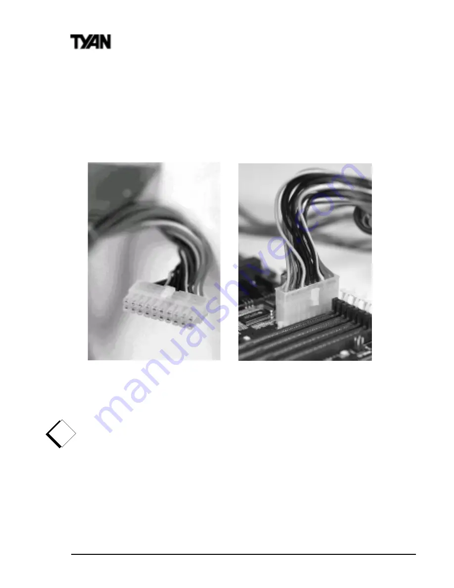
The Trinity KT requires an ATX power supply.  Tyan recommends using one that

conforms to industry standard revision 2.01. The photos below show the ATX power

connector before (

Figure 2-12

) and after (

Figure 2-13

) it has been plugged in. The

plastic clip on the power connector should lock over the plastic tab on the onboard

connector.  You shouldn’t be able to plug the power connector in any other way but

just to be safe, make sure it looks like 

Figure 2-13

 below.

Make certain that you do not miss connecting any pins because if you do, you will

void your warranty and cause damage to yourself or your motherboard when you turn

the system on.  After connecting the power, make sure the connector is seated firmly

into its socket so it will not become loose or fall off when the computer is jostled or

moved. 

NOTE: When installing your power supply, make sure the power supply

switch is turned ‘OFF’. You may turn the switch back ‘ON’ once you’ve finished

building your system.

You are done!

Other than checking the jumper settings and cable connections, and putting the case

back on, you are done. Installing a new motherboard may sound difficult, but by

following these directions, you should have a fairly uneventful time installing our

products. If you do encounter problems, your dealer will be able to help you, or you

can consult one of our many technical support resources (see page 8).

Chapter 2

Board Installation

!

important!

Figure 2-13

Figure 2-12

Summary of Contents for S2390 TRINITY KT

Page 1: ...ix Software Windows is a trademark of Microsoft Corporation IBM PC AT PS 2 are trademarks of IBM Corporation Duron and Athlon are trademarks of Advanced Micro Devices Trinity KT is a trademark of Tyan Computer Corporation Information contained in this publication has been carefully checked for accuracy and reliability In no event will Tyan Computer be held liable for any direct or indirect inciden...

Page 2: ...ounting the Motherboard in the Chassis 18 Installing Memory 18 Installing the CPU and Cooling Fan 21 Connecting IDE and Floppy Drives 21 Installing Add on Cards 24 Connecting PS 2 USB Serial and Parallel Devices 25 Connecting the Power Supply 26 Frequently Asked Questions 27 3 BIOSConfiguration 28 MainSetup 31 Standard CMOS Features 32 Advanced BIOS Features 36 Advanced Chipset Features 40 Integra...

Page 3: ...4 SystemResources 56 BeepCodes 56 Troubleshooting System Problems 57 Displayed Error Messages 57 Appendix Glossary 60 ...

Page 4: ...ng animation and video production This integrated high performance system board in an ATX form factor offers more features and expandability than other ATX boards in its class Some of the features included are onboard UltraDMA 33 66 and optionally onboard digital link sound with Via 686A sound chipset utilizing the AC 97 audio codec Flexibility and expandability have also been designed into the Tr...

Page 5: ...ystem which are indicated by this icon However it is in your best interest to read an entire section and perhaps the entire manual before you begin to install your motherboard While we have alerted you to potential dangers in several places in the manual with this icon these warnings should not be regarded as the whole of your safety regimen Never forget that computers are electrical devices and a...

Page 6: ...nitoring headers Flexible temperature and voltage sensing 3 pin Wake on LAN header 3 pin Wake on Ring header Memory Three 168 pin 3 3V unbuffered DIMM sockets Supports up to 1 5 GB through PC100 registered 512 MB DIMMs ECC memory is NOT supported except for PC100 registered 512 MB DIMMs Supports PC100 133 SDRAM unregistered non ECC and VCM SDRAM Integrated PCI IDE Dual channel master mode Supports...

Page 7: ...toring Mutliple boot options DMI 2 0 compliant Form Factor ATX 2 03 12 x 8 2 Four layer board One 20 pin ATX power connector Stacked mouse and keyboard ports Stacked one serial port and one parallel port Stacked two USB ports Stacked audio and MIDI Game ports optional Regulatory FCC Class B Declaration of Conformity European Community CE Declaration of Conformity INTRO Check the Tyan website for m...

Page 8: ...driver updates etc http www tyan com 3 Contact your dealer or distributor for help BEFORE calling Tyan 4 Check the Tyan user group alt comp periphs mainboard tyan Returning Merchandise for Service During the warranty period contact your distributor or system vendor FIRST for any product problems This warranty only covers normal customer use and does not cover damages incurred during shipping or fa...

Page 9: ...S2390 Trinity KT 9 INTRO This page left blank intentionally ...

Page 10: ...al 1 Driver CD Installation You are now ready to install your motherboard The mounting hole pattern of the Trinity KT matches the ATX system board specifications Your chassis should support a standard ATX mainboard form factor How to install our products right the first time What s the first thing I should do The first thing you should do is read this user s manual It contains important informatio...

Page 11: ...static bag hold it by its edges and place it on a grounded antistatic surface component side up Inspect the board for damage DO NOTAPPLY POWER TO THE BOARD IFIT HAS BEEN DAMAGED Press down on any of the socket ICs if it appears that they are not properly seated the board should still be on an antistatic mat Do not touch the bottom of the board Remember don t take any electronic device out of its p...

Page 12: ...stic jumper connector overtop of two adjacent jumper pins indicated by 1 2 or 2 3 The metal rod inside the plastic shell bridges the gap between the two pins completing the circuit See Figure 2 2 for more example of pin connections Figure 2 1 Figure 2 2 The tables and maps on the following pages will help you set the jumpers for CPU speed Infrared and external connector pin assignments among other...

Page 13: ...L Mouse Keyboard 2 USB Ports Printer Port Power Supply FAN1 AMD Athlon Socket A 500 MHz to 1 GHz 3 DIMM Sockets Game Port S IDE FAN2 P IDE 1 AGP 1x 2x 4x VIA KT 133 Battery VIA 686A Southbridge BIOS CD Audio in Video in JP24 J1 COM2 JP22 JP21 J2 6 32 bit PCI slots 1 ISA slot COM1 Port Temperature Monitor JP18 JP1 Internal Buzzer FDD WOM1 WOL1 Mic Line in Line out ...

Page 14: ...slots PS 2 Mouse Keyboard ports Floppy connector Parallel COM1 ports Joystick port mic line in line out ISA slot Socket A Type for Athlon CPU 2 USB ports Primary IDE Secondary IDE ATX Power Supply Header Battery AGP 2x 4x slot VIA KT 133 chipset 6 PCI slots Internal Buzzer Award BIOS Video In CD Audio ...

Page 15: ... incorrectly follow the instructions below 1 Power off the system and disconnect the power supply 2 Set jumper JP21 to pins 2 and 3 3 Wait for 10 seconds then return jumper JP21 to pins 1 and 2 4 Power on the system again By following this procedure you will erase your password and reset the CMOS to the BIOS defaults 1 D Wake On Modem Connector optional WOM1 1 E Wake On LAN Connector optional WOL1...

Page 16: ... plug in cards Certain applications associated with these plug in cards use the interface for hardware control and queries 1 L Power Management JP18 STR is part of the ACPI system which provides energy saving functions for the computer If this jumper is set to NOT ENABLED close pins 2 3 which is the default setting the system will default to S1 state even if the BIOS has ACPI functions enabled If ...

Page 17: ...r button down for four seconds Hardware Reset Switch Connector Installation The Reset switch on your case s display panel provides you with the Hardware Reset function which is the same as power on off The system will do a cold start after the Reset button is pushed CMOS RTC The Real Time Clock RTC circuit which provides the date and time for the system is integrated into the KT 133 chipset If the...

Page 18: ...races in the surrounding area The hole you should use is located at the top center of the board where the adapter cards are fastened to the case 3 Installing Memory Since Tyan boards are manufactured with performance in mind you should use add in components that match Some DIMM modules may seem to be high quality because of name or feel but that does not guarantee real world usability Some cheaper...

Page 19: ...M can fit properly Make sure that the short row of pins is lined up with the short gap in the DIMM slot Figure 2 3 previous page shows how to sit the DIMM into its slot To insert the DIMM push down vertically on the module with even force as shown in the photo Do not shove one end in first doing so will bend the DIMM pins To lock the DIMM into place push the plastic clips on either end of the slot...

Page 20: ...configurations are listed Warning DO NOT use registered DIMMs with exception to 512 MB PC100 registered memory Check with your memory dealer for more information See www tyan com for the latest memory compatibility information 1 k n a B M M I D 2 k n a B M M I D 3 k n a B M M I D l a t o T 1 x B M 2 3 1 x B M 2 3 0 B M 4 6 0 1 x B M 2 3 1 x B M 2 3 4 6 B M 1 x B M 4 6 1 x B M 2 3 0 B M 6 9 0 B M 2...

Page 21: ... down lightly on the CPU and lower the arm on the ZIF socket to secure the CPU A squeaking noise is normal as the arm lowers After the CPU is securely seated install the appropriate cooling device Tyan strongly recomends a heatsink fan combination Consult with your case manufacturer for other cooling options Locate the cooling fan connector e g FAN1 on the motherboard Plug the CPU s cooling fan ca...

Page 22: ...gacy IDE drives Note The BLUE end of the ATA 66 cable must connect to the motherboard Only Tyan approved cables will work on this motherboard If you are using an existing case with old cables your system may not function properly Some symptoms of incorrectly installed HDDs are Hard disk drives are not auto detected may be a Master Slave problem or a bad IDE cable Contact your vendor Hard Disk Driv...

Page 23: ...rrent floppy drives on the market require that the colored stripe be positioned so that it is right next to the power connector In most cases there will be a key pin on the cable which will force you to connect the cable properly INSTALL 1 Figure 2 10 Figure 2 9 Note The images above is used to illustrate a concept and may not represent the actual image of your motherboard Pin 1 ...

Page 24: ...ing in a card In order to assure proper operation and a quick installation adhere to these guidelines If you are going to install a soundcard the onboard sound must be manually disabled through the BIOS first If you are going to install a PCI Bus interface card on your system be aware that any one of the 6 PCI slots can support a Master or Slave device NEVER force a card into a slot If it doesn t ...

Page 25: ...S 2 port The PS 2 connectors are probably quite familiar to you while the Universal Serial Bus USB connectors may not be The USB port can function as a serial parallel mouse keyboard or joystick port It is fast enough to support video transmissions and is capable of supporting up to 127 daisy chained peripheral devices Figure 2 11 below shows the ATX double row connectors on this board The Serial ...

Page 26: ...or your motherboard when you turn the system on After connecting the power make sure the connector is seated firmly into its socket so it will not become loose or fall off when the computer is jostled or moved NOTE When installing your power supply make sure the power supply switch is turned OFF You may turn the switch back ON once you ve finished building your system You are done Other than check...

Page 27: ...n motherboards A Please refer to URL link here http www tyan com techref html io_usb html Q My motherboard is dead how do I return it A Contact the place of purchase or your distributor for assistance to return the motherboard for service RMA issues will not be handled via email by Tyan Tech Support Please refer to URL link here for more details http www tyan com support html rma_faq html Q How do...

Page 28: ...s the Award BIOS Setup program The Setup program lets you modify basic system configuration settings The settings are then stored in a dedicated battery backed memory called NVRAM that retains the information when the power is turned off The Award BIOS in your computer is a customized version of an industry standard BIOS for IBM PC AT compatible personal computers It supports Intel x86 and compati...

Page 29: ...essage appears briefly at the bottom of the screen during POST TO ENTER SETUP BEFORE BOOT PRESS DEL KEY If the message disappears before you respond and you still wish to enter Setup restart the system to try again by turning it OFF then ON or pressing the RESET button on the system case You may also restart by simultaneously pressing Ctrl Alt and Delete keys If you do not press the keys at the co...

Page 30: ...1 8S DUURZ 0RYH WR SUHYLRXV LWHP RZ Q DUURZ 0RYH WR QH W LWHP HIW DUURZ 0RYH WR LWHP RQ WKH OHIW VLGH 5LJKW DUURZ 0RYH WR LWHP RQ WKH ULJKW VLGH 6 NH 0DLQ 0HQX 4XLW DQG GR QRW VDYH FKDQJHV LQWR 026 5 0 6WDWXV 3 DJH 6HWXS 0HQX LW FXUUHQW SDJH DQG UHWXUQ WR 0DLQ 0HQX 3J8S NH QFUHDVH WKH QXPHULF YDOXH RU PDNH FKDQJHV 3J Q NH HFUHDVH WKH QXPHULF YDOXH RU PDNH FKDQJHV QFUHDVH WKH QXPHULF YDOXH RU PDNH ...

Page 31: ...nu similar to the one shown below appears on the screen The Main Menu allows you to select from several Setup functions and two exit choices Use the arrow keys to select among the items and press enter to accept and enter the sub menu A brief description of each highlighted selection appears at the bottom of the screen Following is a brief summary of each Setup category CMOS Setup Utility Copyrigh...

Page 32: ...SWLRQV LQ WKH RULJLQDO 3 7 FRPSDWLEOH 26 GYDQFHG 26 HDWXUHV Z DUG 6RIWZ DUH HQKDQFHG 26 RSWLRQV GYDQFHG KLSVHW HDWXUHV 2SWLRQV VSHFLILF WR RXU V VWHP FKLSVHW QWHJUDWHG 3HUSKHUDOV 2 VXEV VWHPV WKDW GHSHQG RQ WKH LQWHJUDWHG SHULSKHUDOV FRQWUROOHU LQ RXU V VWHP 3RZ HU 0DQDJHP HQW 6HWXS GYDQFHG 3 RZ HU 0DQDJHPHQW 3 0 RSWLRQV 3Q3 3 RQILJXUDWLRQV 3 OXJ DQG 3 OD VWDQGDUG DQG 3 RFDO XV FRQILJXUDWLRQ RSWLR...

Page 33: ...specifications of your installed IDE hard drive s with the preprogrammed values for drive types 1 through 45 2 Select User and enter values into each drive parameter field 3 Use the IDE HDD Auto Dectection function in Setup CMOS Setup Utility Copyright C 1984 2000 Award Software Standard CMOS Features Date mm dd yy Sat Jan 1 2000 Item Help Time hh mm ss 0 10 30 Menu Level IDE Primary Master Press ...

Page 34: ... Landing zone Sector Number of sectors Access Mode Auto Normal large or LBA Drive A Select the correct specifications for the diskette drive s installed in the computer XWR 7KH 26 DXWRPDWLFDOO GHWHUPLQHV WKH RSWLPDO PRGH 1RUP DO 0D LPXP QXPEHU RI F OLQGHUV KHDGV DQG VHFWRUV VXSSRUWHG DUH DQG DUJH RU GULYHV WKDW GR QRW VXSSRUW DQG KDYH PRUH WKDQ F OLQGHUV RJLFDO ORFN GGUHVVLQJ XULQJ GULYH DFFHVVHV ...

Page 35: ... 9 QKDQFHG UDSKLFV GDSWHU 9LGHR UDSKLFV UUD RU 9 6 69 RU 3 PRQLWRU DGDSWHUV RORU UDSKLFV GDSWHU SRZ HU XS LQ FROXPQ PRGH RORU UDSKLFV GDSWHU SRZ HU XS LQ FROXPQ PRGH 0212 0RQRFKURPH DGDSWHU LQFOXGHV KLJK UHVROXWLRQ PRQRFKURPH DGDSWHUV 1R HUURUV 3 267 GRHV QRW VWRS IRU DQ HUURUV OO HUURUV I WKH 26 GHWHFWV DQ QRQ IDWDO HUURU 3 267 VWRSV DQG SULPSWV RX WR WDNH FRUUHFWLYH DFWLRQ OO EXW NH ERDUG 3 267 ...

Page 36: ...ce Floppy the VIRUS warning Second Boot Device HDD 0 feature for IDE Hard Third Boot Device LS120 Disk boot sector Boot Other Device Enabled protection If this Swap Floppy Drive Disabled function is enabled Boot UpFloppy Seek Enabled and someone attempts Boot Up NumLock Status On to write data into this Gate A20 Option Normal area BIOS will show a Typematic Rate Setting Disabled warning message on...

Page 37: ...MOS Features Virus Warning Disabled Item Help CPU Internal Cache Enabled External Cache Enabled Menu Level CPU L2 Cache ECC Checking Enabled Quick Power On Self Test Disabled Allows you to choose First Boot Device Floppy the VIRUS warning Second Boot Device HDD 0 feature for IDE Hard Third Boot Device LS120 Disk boot sector Boot Other Device Enabled protection If this Swap Floppy Drive Disabled fu...

Page 38: ...ppy Drive This option allows you to swap the floppy drives if more than one is installed It allows you to switch the A and B to make B become A Boot Up Floppy Seek When Enabled the BIOS tests seeks floppy drives to determine whether they have 40 or 80 tracks Only 360 KB floppy drives have 40 tracks drives with 720 KB 1 2 MB and 1 44 MB capacity all have 80 tracks Because very few modern PCs have 4...

Page 39: ...ware such as the system BIOS video BIOS and similar operating instructions that come with some expansion peripherals such as for example a SCSI adapter Shadowing copies firmware from ROM into system RAM where the CPU can read it through the 16 bit or 32 bit DRAM bus Firmware not shadowed must be read by the system through the 8 bit X bus Shadowing improves the performance of the system BIOS and si...

Page 40: ...ns Menu Level Bank 6 7 DRAM Timing SDRAM 5 10ns SDRAM Cycle Length 3 DRAM Clock Host CLK Memory Hole Disabled P2C C2P Concurrency Enabled Fast R W Turn Around Disabled System BIOS Cacheable Disabled Video RAM Cacheable Disabled AGP Aperature Size 64M AGP 4X Mode Enabled AGP Driving Control Auto X AGP Driving Value DA AGP Fast Write Disabled OnChip USB Disabled USB Keyboard Support Disabled CPU to ...

Page 41: ...ng SDRAM 5 10ns Bank 4 5 DRAM Timing SDRAM 5 10ns Menu Level Bank 6 7 DRAM Timing SDRAM 5 10ns SDRAM Cycle Length 3 DRAM Clock Host CLK Memory Hole Disabled P2C C2P Concurrency Enabled Fast R W Turn Around Disabled System BIOS Cacheable Disabled Video RAM Cacheable Disabled AGP Aperature Size 64M AGP 4X Mode Enabled AGP Driving Control Auto X AGP Driving Value DA AGP Fast Write Disabled OnChip USB...

Page 42: ...ry AGP Aperture Size Select the size of the Accelerated Graphics Port AGP aperture The aperture is a portion of the PCI memory address range dedicated for graphics memory address space Host cycles that hit the aperture range are forwarded to the AGP without any translation See http www agpforum org forAGPinformation AGP 4x Mode Enables the 4X AGP mode for higher AGP throughput A 4X AGP graphics ca...

Page 43: ...buffer Burstable transactions then burst on the PCI bus nonburstable transactions do not PCI Master 0 WS Write When this field is Enabled writes to the PCI bus are executed with zero wait states PCI Delay Transaction The chipset has an embedded 32 bit posted write buffer to support delay transaction cycles Select Enabled to support compliance with PCI specification version 2 1 PCI 2 Access 1 Retry...

Page 44: ...ry Master PIO Auto Secondary Slave PIO Auto Primary Master UDMA Disable Primary Slave UDMA Disable Secondary Master UDMA Disable Secondary Slave UDMA Disable Init Display First PCI Slot IDE HDD Block Mode Disabled KBC input clock 8 MHz Onboard FDD Controller Enabled Onboard Serial Port 1 3F8 IRQ4 Onboard Serial Port 2 2F8 IRQ3 UART Mode Select Normal X UART2 Duplex Mode Half X RxD TxD Active Hi Lo...

Page 45: ...grated Peripherals OnChip IDE Channel0 Enabled Item Help OnChip IDE Channel1 Enabled IDE Prefetch Mode Enabled Menu Level Primary Master PIO Auto Primary Slave PIO Auto Secondary Master PIO Auto Secondary Slave PIO Auto Primary Master UDMA Auto Primary Slave UDMA Auto Secondary Master UDMA Auto Secondary Slave UDMA Auto Init Display First PCI Slot IDE HDD Block Mode Enabled KBC input clock 8 MHz O...

Page 46: ...d in your system IDE HDD Block Mode Block mode is also called block transfer multiple commands or multiple sector read write If your IDE hard drive supports block mode most new drives do select Enabled for automatic detection of the optimal number of block read writes per sector the drive can support KBC Input Clock Allows you to adjust the keyboard clock signal Onboard FDC Controller Select Enabl...

Page 47: ...r to select a mode for the onboard parallel port ECP Mode Use DMA Allows the parallel ports to enable DMA this a faster transfer rate EPP Mode Select This setting selects the printer port s data transfer mode PWRON After PWR Fail This function enables the computer to power up or down after a sudden power interruption If the setting is set to OFF the computer will stay off even if the power is resu...

Page 48: ...4 2000 Award Software Power Management Setup ACPI Function Enabled Item Help Power Management Press Enter Video Off Option Suspend Off Menu Level Video Off Method V H SYNC Blank MODEM Use IRQ 3 Soft Off by PWRBTN Instant Off Wake Up Events Press Enter Move Enter Select PU PD Value F10 Save ESC Exit F1 General Help F5 Previous Values F6 Fail Safe Defaults F7 Optimized Defaults w w w 0D 6DYLQJ 0D LP...

Page 49: ...operate at full speed Suspend Mode After the selected period of system inactivity 1 minute to 1 hour all devices except the CPU shut off ACPI Suspend Type This setting controls the type of suspend function that is enabled once the computer has gone into suspend mode CMOS Setup Utility Copyright C 1984 2000 Award Software Power Management Power Management User Define Item Help HDD Power Down Disabl...

Page 50: ...utton places the system in a very low power usage state either immediately or after 4 seconds with only enough circuitry receiving power to detect wake up event activity Wake Up Events A power management PM event awakens the system from or resets activity timers for Suspend mode 9 6 1 ODQN 6 VWHP WXUQV RI I YHUWLFDO DQG KRUL RQWDO V QFKURQL DWLRQ SRUWV DQG Z ULWHV EODQNV WR WKH YLGHR EXIIHU 306 6X...

Page 51: ... power up through a LAN connection when used in conjunction with a Wake on LAN compliant network adapter and appropriate software CMOS Setup Utility Copyright C 1984 2000 Award Software Wake Up Events VGA OFF Item Help LPT COM LPT COM HDD FDD ON Menu Level DMA Master OFF Wake Up On LAN Disabled Modem Ring Resume Disabled RTC Alarm Resume Disabled X Date of Month 0 X Resume Time hh mm ss 0 0 0 Prim...

Page 52: ...ondary wake up When Primary INTR is On the IRQs in the above fields can be configured as Primary Secondary or Disabled IRQn The following is a list of IRQs Interrupt Request Lines assigned to common system peripherals IRQ0 System Timer IRQ7 LPT1 IRQ1 Keyboard IRQ8 RTC Alarm IRQ2 Cascade Reserved IRQ9 FREE IRQ3 COM2 IRQ10 FREE IRQ4 COM1 IRQ11 FREE IRQ5 FREE IRQ12 PS 2 Mouse IRQ6 Floppy Disk IRQ13 C...

Page 53: ...ces Controlled By The Plug and Play EliteBIOS can automatically configure all the boot and Plug and Play compatible devices If you select Auto all the interrupt request IRQ and DMA assignment fields disappear because the BIOS automatically assigns them CMOS Setup Utility Copyright C 1984 2000 Award Software PnP PCI Configurations PNP OS Installed NO Item Help Reset Configuration Data Disabled Menu...

Page 54: ... a specific DMA channel PCI ISA PnP Devices compliant with the Plug and Play standard whether designed for PCI or ISA bus architecture PCI VGA Palette Snoop Please leave this field at Disabled Assign IRQ for VGA Assign an IRQ number to your VGA adapter Assign IRQ for USB Assign an IRQ number to your USB device controller PC Health Status Note This chapter describes all fields offered by Award Soft...

Page 55: ...r to get the Flash Utility For more information and updates about the Flash Utilities check the Tyan web site at http www tyan com To flash the BIOS do this i Boot system to DOS make sure you are not under Windows check your Windows documentation for details on how to boot to DOS only ii Type flash4mb followed by ENTER key iii To save or not save the old BIOS is up to you iv Type in the BIOS filen...

Page 56: ...ess are communicated through a series of audible beeps If AwardBIOS POST can initialize the system video display it displays the error message Displayed error messages in most cases allow the system to continue to boot Displayed error messages are described on pages 58 59 See the top of the next page for the beep code chart ...

Page 57: ...ed Error Messages If an error occurs after the system display has been initialized the error message will be displayed as follows ERROR Message Line 1 ERROR Message Line 2 Press F1 to continue and the system will halt Depending on how the Halt On setting was configured in the Standard CMOS Setup menu the system may or may not display the error message RUN SETUP UTILITY may also appear Press F1 to ...

Page 58: ... a l p e R w o l s i r e w o p y r e t t a b e h T y r e t t a b a y b d e r e w o p s i M A R S O M C m u s k c e h C S O M C e r u l i a F p u t e S S O I B N I W n u R e u l a v s u o i v e r p e h t n a h t t n e r e f f i d s i m u s k c e h c M A R S O M C s n o i t p O m e t s y S S O M C t e S t o N p u t e S S O I B N I W n u R d e y o r t s e d n e e b e v a h M A R S O M C n i d e r o t...

Page 59: ... d a e r n a c S O I B I M A n e e r c s e h t w o l l o f d n a e t t e k s i d t o o b r e h t o n a e s U t i h t i w m e t s y s s n o i t c u r t s n i s I d r a o b y e K t I k c o l n U d e k c o L e b t s u m m e t s y s e h T d e g a g n e s i m e t s y s e h t n o k c o l d r a o b y e k e h T t o o b o t e u n i t n o c o t d e k c o l n u r o r r E d r a o b y e K r e l l o r t n o C d...

Page 60: ... used on Intel Reference Motherboard platforms using Intel s core logic chipsets supporting AC Link 2 1 It supports fax and all data feeback modes It provides high speed communicstions between your perosn al computer and a remote location such as an Internet Service Provider ISP AT was the original form factor of IBM s PC ATAPI ATAttachment Packet Interface also known as IDE or ATA is a drive impl...

Page 61: ...rash Information stored in a buffer is temporarily stored not permanently saved A bus is a data pathway The term is used especially to refer to the connection between the processor and system memory and between the processor and PCI or ISA local buses Bus mastering allows peripheral devices and IDEs to access the system memory without going through the CPU similar to DMA channels A cache is a temp...

Page 62: ... unit are the same That is one DIMM module fits into one DIMM socket which is capable of acting as a memory bank DMA Direct Memory Access channels are similar to IRQs DMA channels allow hardware devices like sound cards or keyboards to access the main memory without involving the CPU This frees up CPU resources for other tasks As with IRQs it is vital that you do not double up devices on a single ...

Page 63: ...tegrated Device or Drive Electronics is a simple self contained hard drive interface It can handle drives up to 8 4GB in size Almost all IDEs sold now are in fact Enhanced IDEs EIDEs IDE INT IDE Interrupt is a hardware interrupt signal that goes to the IDE I O Input Output is the connection between your computer and another piece of hardware mouse keyboard etc IRQ An Interrupt Request is an electr...

Page 64: ...lly larger Data is cached first to the faster primary cache and then when the primary cache is full to the slower secondary cache Pipelining improves system performance by allowing the CPU to begin executing a second instruction before the first is completed A pipeline can be likened to an assembly line with a given part of the pipeline repeatedly executing a set part of an operation on a series o...

Page 65: ...bank and act as a unit If only one socket is filled the bank will not operate In Sleep Suspend mode all devices except the CPU shut down SRAM Static RAM unlike DRAM does not need to be refreshed in order to prevent data loss Thus it is faster and more expensive In Standby mode the video and fixed disk drive shut down all other devices operate normally UltraDMA 33 66 100 is a fast version of the ol...

Page 66: ... an outlet on a circuit different from that of the receiver Consult the dealer or an experienced radio television technician for help Notice for Canada This apparatus complies with the Class B limits for radio interference as specified in the Canadian Department of Communications Radio Interference Regulations Cet appareil est conforme aux normes de Classe B d interference radio tel que spécifié p...

Reviews: