6
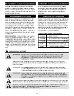
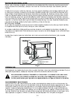
The control panel is located on the upper-right corner of the electric
fireplace insert.
-
POWER
• When turning off the fireplace the latest settings will be stored in the memory.
If the fireplace is unplugged the memory will be reset.
• Holding the power button on the control panel for 10 seconds will disable
the heater function. Press and hold the button again for 10 seconds
to re-enable.
- FLAME
• Press the flame button to cycle through the flame settings between constantly
on, auto and off.
• There are 6 flame setting you can cycle through the UP and DOWN arrows.
• There are HI and LOW auto setting cycle through the UP and DOWN arrows.
- FAN
• Press the fan button to turn on and off the fan.
- HEATER
• Press the heater button to turn the heater on or off.
• The default thermostat setting is 72°F (22°C). The set range is 50 - 97 °F
(10 - 36 °C) or always ON.
• Use the UP and DOWN arrow buttons to set the desired thermostat setting.
• The heater will run until the ambient temperature reaches the thermostat
setting. The heater will then cycle on and off to maintain the temperature.
• To change between °F and °C press and hold the heater button on the
control panel for 3 seconds.
• If the space being heated is too large or poorly insulated, the ambient
temperature may not reach the thermostat setting and the heater will
run continuously.
• As a safety feature, the fan will continue to blow for several minutes to cool
the internal components after the heater is turned off.
- TIMER
• Press the timer button to switch the Timer ON and OFF.
• Use the UP and DOWN arrow buttons to set the timer length. The timer
settings are: 30 minutes, 1 hour, 2H, 3H, 4H, 5H, 6H, 7H, 8H, and 9H.
• The fireplace will shut-off automatically once the set time has elapsed.
- DOWNLIGHT
• Press the downlight button to switch the downlight settings between
ON, undulation and OFF.
• Setting 1 is constantly on.
• Setting 2 causes the downlight to undulate slowly to mimic the light
given off by flickering flames.
OPERATING INSTRUCTIONS
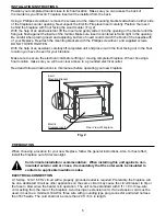
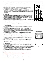
Fig . 3
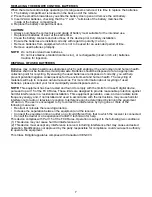
Fig . 4
REMOTE CONTROL
CONTROL PANEL


