INSTRUCTION MANUAL
Please read this manual throughly before use and keep it handy for future reference
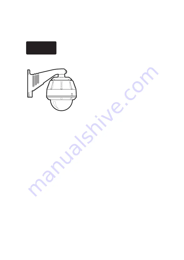
700TV
Hi
gh
Speed Dome Camera
User Manual
Page 1: ...INSTRUCTION MANUAL Please read this manual throughly before use and keep it handy for future reference 700TV High Speed Dome Camera User Manual ...
Page 2: ...MATION THIS EQUIPMENT HAS BEEN TESTED AND FOUND TO COMPLY WITH THE LIMITS FOR A CLASS A DIGITAL DEVICE PURSUANT TO PART 15 OF THE FCC RULES THESE LIMITS ARE DESIGNED TO PROVIDE REASONABLE PROTECTION AGAINST HARMFUL INTERFERENCE WHEN THE EQUIPMENT IS OPERATED IN A COMMERCIAL ENVIRONMENT THIS EQUIPMENT GENERATES USES AND CAN RADIATE RADIO FREQUENCY ENERGY AND IF NOT INSTALLED AND USED IN ACCORDANCE ...
Page 3: ...durability extremely reliability This camera offers perfect prevention of dew condensation and clear image at operating temperature from 50 50 Especially this mechanism supports greatly increase accuracy and decreasing operation noise With an accuracy position it can precisely maintain preset camera positions even after frequent panning and tilting Also it offers perfect control of camera mechanis...
Page 4: ...able Wiring DIMENSION SPECIFICATION OPERATION PROGRAMMING Menu Tree Check point Programming System Information Reboot Factory Event Log Password Dispaly OSD Setup Area Title Privacy Zone Image Setup Dome General Motion Home Preset Tour Pattern Scan Camera Focus Zoom White Balance Exposure Advanced Setup Reset Alarm 2 3 4 5 6 7 8 9 9 10 10 11 12 12 12 13 13 13 14 14 14 15 15 16 16 16 17 17 18 18 19...
Page 5: ...Wrench Manual 1 1 1 1 1 Precautions The following steps of installation and connection work should be done by qualified service personal or system installers and should conform to all local codes Be sure to switch the camera off before installation and connection Do not install the camera beside air outlet of an air conditioner STEP 4 Remove the airbag Open the screw for dome camera unit Take out ...
Page 6: ...table C for details Switch1 Switch 2 Protocols Off Off Pelco D Pelco P etc Auto detect Switch3 Switch 4 Baud Rate bps Off Off 2400 default Off On 4800 On Off 9600 On On 38400 Switch5 Termination Off Not Terminated default On Terminated Protocols Setting If you are going to use pelco D pelco P protocols to communicate with the dome system you do not have to set any switches The unit automatically d...
Page 7: ... When you assemble the dome bubble Ass y Please follow up the picture STEP 4 Connect the dome bubble Ass y to the housing body Ass y Wall Mount Installation STEP 1 Fix the TP 18 x 30L Screw supplied NO Parts Name DESCRIPTION Q ty 2 Monut Screw TP1 8 x 30L 4 1 Wall Mount Bracket AL Diecasting 1 STEP 2 Pass the cables through the bottom of the bracket STEP 3 Hang the safety hook against drop on the ...
Page 8: ...ket cover and fix it by knob bolt Fix the steel cover supplied on the upper of the bracket using screw CM3x8L Ceiling Mount Installation STEP 1 Fix the plastic anchors on the ceiling as this figure and fix the ceiling using the screws supplied STEP 2 Fix the pipe supplied as this figure turning it clockwise STEP 3 Connect the camera and the bracket cable and fix it turning the camera set clockwise...
Page 9: ...lack Orange Green Brown White Red White Orange Black Brown Yellow Black Green White Blue White Alarm 0 Alarm 1 Alarm 2 Alram 3 NO COM NC GND GND RS 485 RS 485 1 2 3 4 5 6 7 8 9 10 11 2 3 3 0 110 0 300 9 300 9 16 0 16 0 261 0 261 0 322 3 322 3 211 3 211 3 471 6 279 3 471 6 279 3 170 0 277 3 235 0 233 0 TINT COLOR BRIGHT CONT V1 VOLUME UNDER SCAN S VIDEO POWER V2 PMC14H Video Power ...
Page 10: ...prox 5 5kg IF you use Peoco D or Pelco P protocol in your controller you can access the main menu by programming saving or calling preset 95 STARTING OSD MENU NENU PRESET 95 SYSTEM DISPLAY DOME CAMERA ALARM EXIT OSD SETUP AREA TITLES PRIVACY ZONE IMAGE SETUP FOCUS ZOOM W BALANCE EXPOSURE ADVANCED INFO REBOOT FACTORY EVENT LOG PASSWORD GENERAL MOTION HOME PRESET TOUR PATTERN SCAN 27X 37X NTSC 27X 3...
Page 11: ...please check the cable carefully The camera ID of the controller must be identical to that of the target camera The camera ID can be checked by reading Rotary switch of the camera If your controller supports multi protocols the protocol must be changed to match to that of the camera If you change the camera ID by changing Rotary switch the change will be effective after you reboot the camera Since...
Page 12: ...EXIT SYSTEM REBOOT In case of no control or no operating we recommend you should have rebooting Use the following steps to display the system information screen 1 Press the menu key 2 To move the right position by using Joystick 3 Select reboot 4 To reboot the system Press ENT or OPEN To cancel reboot Press ESC or IRIS CLOSE key Reboot ENT OPEN Exit CLR CLOSE Main MENU SYSTEM DISPLAY DOME CAMERA A...
Page 13: ... move Note The default password is 0000 User have to remember it if the password is changed Main Menu SYSTEM INFO DISPLAY REBOOT DOME FACTORY CAMERA EVENT LOG ALARM PASSWORD EXIT PASSWORD CURRENT x NEW CONFIRM ENABLE DISABLED x12456789 Main Menu SYSTEM DISPLAY DOME CAMERA ALARM EXIT DISPLAY OSD SETUP OSD setup allows you to program how labels are displayed on the monitor The following labels are a...
Page 14: ...one 3 Privacy Mask adjust mask size PAN TILT adjust position TELE enlarge sized mask WIDE small sized mask To program a privacy zone 1 Press the MENU key 2 Select DISPLAY PRIVACY ZONE using joystick 3 Use the joystick to position the cursor beside NO xxx and then select zone ID 4 Press the TELE button or twist the joystick to clockwise direction for setup the zone 5 Follow the instructions that ap...
Page 15: ...es at the top of tilt orbit 90 zoom module camera turns on its axis by 180 at the top of tilt orbit and moves to opposite tilt direction 180 to keep tracing targets ON default Auto flip mode is enabled OFF Auto flip mode is disabled OVER TILT To prevent horizontal view due to trim ring or ceiling ON Minimum Tilt Angel is 1 8 degree OFF Minimum Tilt Angle is 4 5 degree AZIMUTH ZERO Azimuth zero is ...
Page 16: ...Press Esc or IRIS CLOSE key to go to previous menu without saving any settings at any time Main Menu SYSTEM DISPLAY GENERAL DOME MOTION CAMERA HOME ALARM PRESET EXIT TOUR PATTERN SCAN PRESET SETUP NO 001 Empty TITLE DWELL PTZ Save and Exit Exit without Saving DOME TOUR The Tour function allows running sequence of presets pattern nd or Tour Max 8 tour can be saved Each group can have Max 30 action ...
Page 17: ... the preset assigned as the 1st Point to the preset assigned as the 2nd point in the direction of the path chosen by the user Then camera moves from the preset assigned as the 2nd point to the preset assigned as the 1st point in the reverse direction To program a scan 1 Press the MENU key 2 Select DOME and select Scan using joystick 3 Use the joystick to position the cursor beside NO xxx Move left...
Page 18: ...Save and Exit Exit without Saving CAMERA W BALANCE This feature automatically processes the viewed image to retain color balance over temperature range The default setting for white balance is auto White Balance has following four modes ATW This mode automatically adjusts color temperature range from 1800K to 10500K It can select INDOOR OUTDOOR and MERCURY mode INDOOR Automatic White Balance for i...
Page 19: ...SHARPNESS Settings ranges from 0 to 15 Enhances picture detail by increasing the aperture gain of the camera and sharpening the edges in the picture BACK LIGHT BLC Back light compensation enhances objects in the center of the picture The dome uses the center of the picture to adjust the iris If there is a bright light source outside of this area it will wash out to white The camera will adjust the...
Page 20: ...ove to joystick and then go to the No xxx alarm number Press the WIDE button or turn the joystick counterclockwise If the joystick is moved the alarm setting will be stopped for 10 sec High Speed Dome Alarm Cable ALARM SETUP NO 001 IN OUT PRIORITY ACTION NUMBER DWELL Save and Exit Exit without Saving Main Menu SYSTEM DISPLAY DOME CAMERA ALARM EXIT 1 2 3 4 Brown White Red White Orange Black Brown A...