


05 MENU OPERATIONS
25
4K /UHD HDR Emulation LCD Monitor
REMOTE (RJ-45)
1: Pin1
2: Pin2
3: Pin3
4: Pin4
5: Pin5
6: Pin6
7: Pin7
8: GND
1
8
PIN No.
Settable Values
PIN
1~6
NONE
SINGLE-SDI
2SI-SDI
QUAD-SDI
HDMI
ASPECT
H/V DELAY
BLUE ONLY
MONO
16:9 MARKER
4:3 MARKER
4:3 ON AIR MARKER
15:9 MARKER
14:9 MARKER
13:9 MARKER
1.85:1 MARKER
2.35:1 MARKER
1.85:1&4:3 MARKER
CENTER MARKER
SAFETY AREA 80%
SAFETY AREA 85%
SAFETY AREA 88%
SAFETY AREA 90%
SAFETY AERA 90%
SAFETY AERA 93%
SAFETY AERA 100%
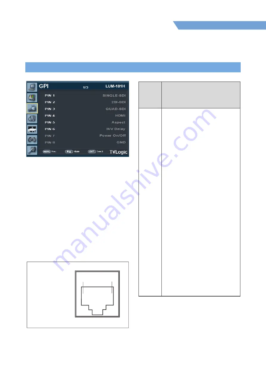
[3] GPI
●
This item activates/ inactivates the
REMOTE function.
●
The user may designate a function for
each pin and each pin’s default setting is
as follows.
●
The default settings are as follows:
PIN 1 : SINGLE-SDI
PIN 2 : 2SI-SDI
PIN 3 : QUAD-SDI
PIN 4 : HDMI
PIN 5 : ASPECT
PIN 6 : H/V Delay
PIN 7 : Power On/Off use only
PIN 8 : GND only
Summary of Contents for LUM-181G
Page 6: ...01 CAUTION 6 4K UHD HDR Emulation LCD Monitor VESA WALL MOUNTING ...
Page 38: ...07 PRODUCT SPECIFICATIONS 38 4K UHD HDR Emulation LCD Monitor ...
Page 39: ...07 OPTIONAL ACCESSORIES 39 4K UHD HDR Emulation LCD Monitor ...
Page 40: ...07 PRODUCT SPECIFICATIONS 40 4K UHD HDR Emulation LCD Monitor ...
Page 42: ...07 PRODUCT SPECIFICATIONS 42 4K UHD HDR Emulation LCD Monitor ...
Page 43: ...07 OPTIONAL ACCESSORIES 43 4K UHD HDR Emulation LCD Monitor ...
Page 44: ......


