


3
MODULE INTERFACES
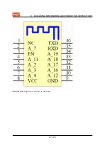
3.2 Pin Definition
The definition of interface pins is shown in the following table:
Pin Number
Symbol
I/O Type
Function
1
NC
/
It is pulled up to
be compatible
with other
modules
2
A_7
I/O
GPIOA_7,
hardware PWM, IC
Pin 21
3
EN
I/O
Enabling pin,
which works at
the high level and
is pulled up and
controlled by a
user externally
4
A_11
I/O
GPIOA_11,
hardware PWM, IC
Pin 25
5
A_2
I/O
GPIOA_2,
hardware PWM, IC
Pin 18
6
A_3
I/O
GPIOA_3,
hardware PWM, IC
Pin 19
7
A_4
I/O
GPIOA_4,
hardware PWM, IC
Pin 20
8
VCC
P
Power supply pin
(3.3V)
9
GND
P
Power supply
reference ground
4 / 25
Summary of Contents for WBR3L
Page 5: ...1 PRODUCT OVERVIEW Baby monitor Network camera Intelligent bus 2 25 ...
Page 17: ...7 POWER ON SEQUENCE AND RESETTING 14 25 ...
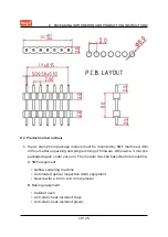
Page 20: ...8 PACKAGING INFORMATION AND PRODUCTION INSTRUCTIONS WBR3L PCB Layout is shown as belows 17 25 ...
Page 25: ...8 PACKAGING INFORMATION AND PRODUCTION INSTRUCTIONS 8 6 Storage Conditions 22 25 ...


