14
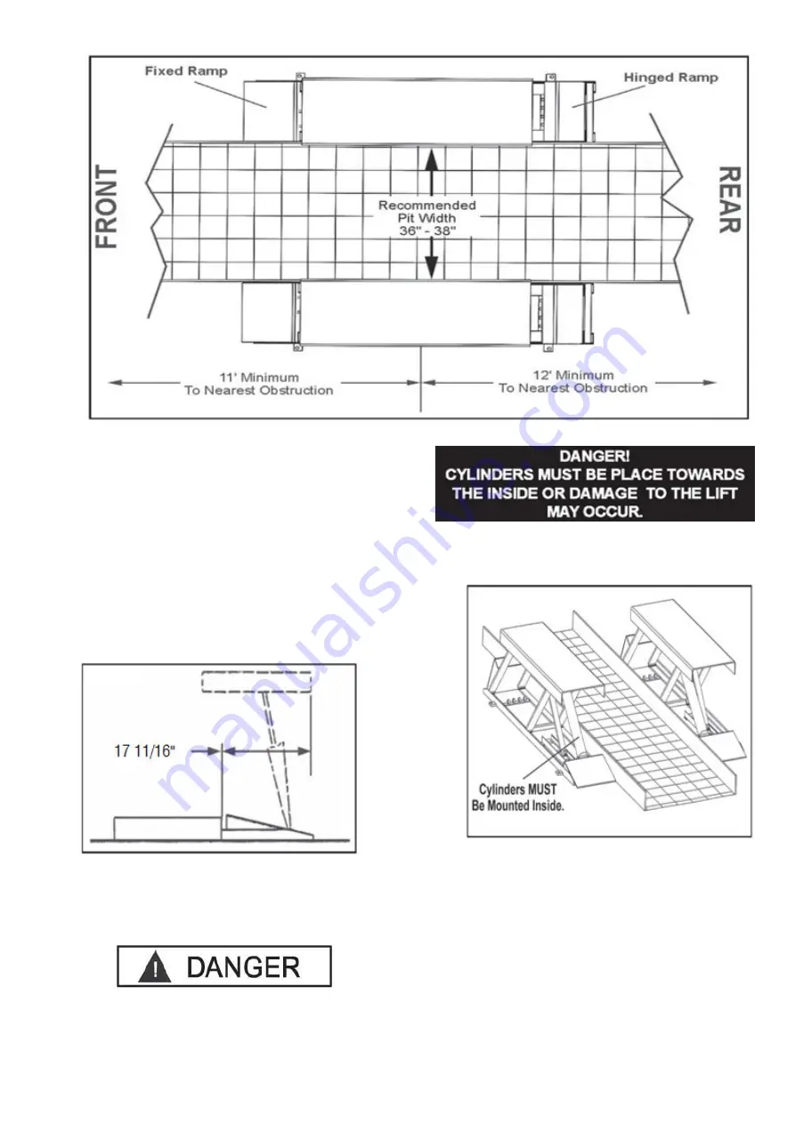
Fig. 3.1
STEP 3
(Locating Unit)
NOTE:
The maximum recommended width between pads is
38”. Consult the factory for applications that require
installations wider than 38”.
1. Before selecting an installation site, check for
proper clearance and/or obstructions. (See Fig
3.1)
2. Remember that the lift moves rearward
approximately 14” when raised. (See Fig 3.2)
Fig. 2.3
3.
Always consult the building engineer before
installing this lift to make sure the floor is capable
of sustaining the load.
4. After selecting a site, place each unit in position.
The Cylinders MUST be placed towards the inside.
(See Fig 3.3)
Fig. 3.3
5. It may be necessary to remove the tire rail
adjacent to the lift pad and overhang the edge of
the rail to maintain the 36”- 38” recommended
width between pads.
6. Each lift pad can overhang the edge of the pit a
maximum of two inches on each side as long as
the inside anchor bolt can be installed properly.
Tire Rail
Summary of Contents for PL6K
Page 1: ...PL6K 6600 POUND CAPACITY LOW RISE PIT Installation and Operation Manual REV A 062813 ...
Page 2: ......
Page 3: ......
Page 25: ...25 6600Lbs 3000Kg 3300Lbs 1500Kg 3300Lbs 1500Kg ...
Page 26: ...26 ...
Page 34: ...34 MAINTENANCE RECORDS ...
Page 35: ...35 ...


