


35
08
Disassembly and Reassembly
Manual 2008 Rev A p/n 2008
Adjusting Interlobe Clearance
23. The outer gear shell is fastened to the
inner hub with four cap screws and located
with two dowel pins. Adding and removing
shims between the gear shell and the inner
hub moves the gear shell axially. The helix
causes the gear to rotate, which changes
the clearance between the rotor lobes.
Adding 0.030 in. (0.762 mm) shim thickness
will change the rotor lobe clearance by
approximately 0.009 in. (0.229 mm).
24. The timing shim is formed from a number of
0.003 in. (0.0762 mm) shims which have been
laminated together. Easily peel them apart as
necessary.
A
B
B
B
A
B
A
A
A
A
B
A
B
B
A
B
LONG FEELER GAUGE
LONG FEELER GAUGE
RECORD A-A
READING HERE
RECORD A-A
READING HERE
RECORD B-B
READING HERE
3 LOBE
2 LOBE
RECORD B-B
READING HERE
B
B
B
B
B
B
B
B
B
B
B
B
A
A
A
A
A
A
A
A
A
A
A
A
DRIVE
DRIVEN
DRIVE
DRIVEN
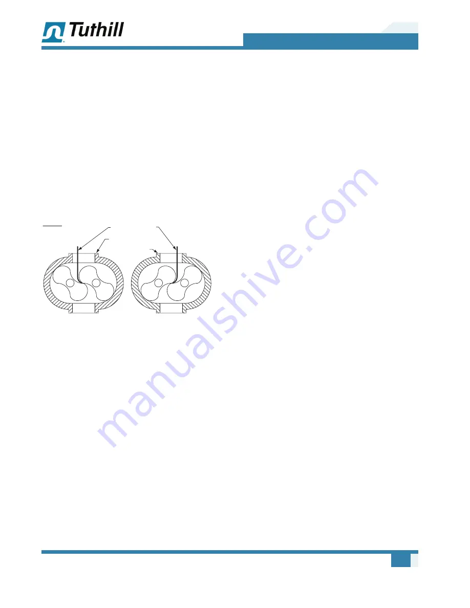
Figure 8-4 – Checking Rotor Interlobe Clearance
25. Use feeler gauges to check the clearance at
AA (right-hand reading) and BB (left-hand
reading) (
see Figure 8-4
). The clearance
should be adjusted so it is as equal between
all lobes as possible, usually between 0.002
to 0.003 in. (0.0508 to 0.0762 mm). For best
results, use feeler gauges no larger than
0.006 in. (0.1524 mm).
Example:
If AA reading is 0.020 in. (0.508
mm) and BB reading is 0.008 in. (0.2032
mm), removing 0.021 in. (0.5334 mm) shims
will change the reading by 0.006 in. (0.1524
mm). AA should read 0.014 in. (0.3556 mm)
and BB should read 0.014 in. (0.3556 mm).
Remember to place timing marks on the center
and match when removing or installing a gear.
Complete Drive End Assembly
26. Clean and remove all burrs from the mating
surfaces of the gear and drive shaft. Install cap
screws. Check drive shaft run-out at the seal.
Do not exceed 0.003 in. (0.0762 mm) T.I.R.
27. Install drive shaft bearing and retainer ring.
If using a top drive unit, install oil slinger and
washer at this time.
28. To aid in the installation of the cover, use a tool
as shown in
Figure 13-2 on page 43
, which
should be made to hold the outer race of the
bearing square with the shaft. Put sealer on
the end plate and slide the cover over the tool
and secure with cap screws.
Complete Drive End Assembly
(Series 17/19/46/55/57/81/82/86)
29. Press seal into adapter. Grease seal and
O-ring and install on shaft. Secure with flat
head screws.
Complete Drive End Assembly
(Series 17/19/46/55/57/81/82/86)
30. Seal into seal housing and install O-ring. Clean
carbon surface and lapped surface of mating
ring with a soft tissue and acetone. Place a few
drops of oil on the mating ring and O-ring and
carefully slide over shaft aligning slot with pin.
Install retainer ring. Install seal housing and
secure with cap screws. Grease and install
O-rings. Install water cooling housing.
Complete Free End Assembly
(Series 17/46/57/64/67/81)
31. Install oil pump drive shaft. Oil slinger and
secure with cap screws. Put sealer on the end
plate and install cover.
Summary of Contents for PD Plus 9000 Series
Page 65: ......


