background image

4

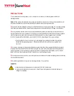
PRECAUTIONS 


1. 

Use filtered air. Avoid grease, oil, or oil vapors, corrosive or reactive gases which will 

damage heater. 

Note: 

When using compressed air a pressure reduction valve and an oil & water separation unit 

should be installed to avoid contaminating the heater and reducing heater life.
 

2. 

Operate at safe voltages as shown on the Performance Curves (see page 11).  Excess voltage 

will cause premature failure.  (See Proper Temperature Controller Setup on Page 7 for details.)

3. 

Using the Max heater with the recommended MAX panels provides improved performance 

and protection from loss of airflow. It is highly recommended that the S1 thermocouple supplied 
with the heater be used with a temperature limiting board to protect against low/no airflow  
(TUTCO SureHeat Part #074835 – set to 300°F/150°C). (See Page 9 for proper wiring)


• If using other forms of control you must always have sufficient airflow through the 

                heater before applying power.  Otherwise element will overheat very quickly, and 
                burn out. 

4. 

If using a process air temperature thermocouple other then the supplied S2 thermocouple it 

is highly recommended that the S2 thermocouple be used with a temperature limiting board to 
protect against over temperature protection (TUTCO SureHeat Part #F074835 – set to 1205°F 
(652°C) for 6 & 10kW units and 1405°F (763°C) for 18, 30 & 36kW units).

5. 

If using closed-loop control, use a temperature controller with a fast sampling period (<500ms) 

and minimal overshoot.  

6. 

Sudden applications of power can damage heater.  To avoid this:

ALWAYS:


a. Return set-point temperature to ambient (70ºF/20ºC) after use.


b. Use a controlled ramp to set-point.  (See Proper Temperature Controller Setup on 

                 Page 7 for details.)

Summary of Contents for Max Air F074723

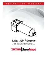
Page 1: ...O P E R A T I N G M A N U A L Max Air Heater FOR SAFETY AND LONG HEATER LIFE CAREFULLY READ THIS MANUAL BEFORE USE ...

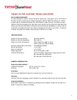
Page 2: ...Maximum Inlet Air Pressure 80 PSI 5 52 BAR Maximum Inlet Air Temperature 200 F 93 C Maximum Exit Air Temperature 1200 F 650 C for 6kW to 10kW 1400 F 760 C for 18kW to 36kW Minimum Airflow Recommended 12 SCFM 340 SLPM Exit Air Connection 1 1 2 FNPT Inlet Air Connection 1 1 4 FNPT Safety Approvals CE UL Recognized CSA Control Limit Sensors Type K isolated ungrounded exposed junction TCs S1 measures ...

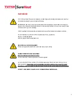
Page 3: ...ls Do not hesitate to contact TUTCO SureHeat with any questions Phone 1 800 258 8290 E Mail support tutcosureheat com ELECTRICAL SHOCK HAZARD Follow all applicable electrical codes and use proper wiring BURN FIRE EXPLOSION HAZARD For use with Air or Inert Gases Only Do not use with or near explosive or reactive gases Avoid contact with the surface of the heater especially the air exit end during o...

Page 4: ...airflow TUTCO SureHeat Part 074835 set to 300 F 150 C See Page 9 for proper wiring If using other forms of control you must always have sufficient airflow through the heater before applying power Otherwise element will overheat very quickly and burn out 4 If using a process air temperature thermocouple other then the supplied S2 thermocouple it is highly recommended that the S2 thermocouple be use...

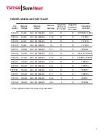
Page 5: ...kW 380 3Ø 50 60Hz 15 2 12 12 F078216 F078136 F074731 10 0kW 480 3Ø 50 60Hz 12 0 12 12 F078135 F074732 18 0kW 240 3Ø 50 60Hz 43 4 8 10 F078136 F074733 18 0kW 380 3Ø 50 60Hz 27 4 10 12 F078217 F074734 18 0kW 480 3Ø 50 60Hz 21 7 12 12 F078135 F074735 30 0kW 380 3Ø 50 60Hz 45 6 8 8 F078217 F074736 36 0kW 480 3Ø 50 60Hz 43 4 8 10 F078136 Follow applicable electrical codes during installation 5 Part Num...

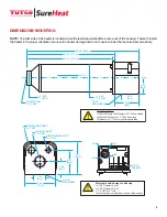
Page 6: ...88 47 8 3 51 98 2 4 75 120 6 4 45 113 0 1 4 20 MTG HOLES SENSOR WIRE PORT 3 8 NPT AIR INLET PORT 1 1 4 NPT POWER WIRE PORT 3 4 NPT 16 00 406 4 12 49 317 2 12 21 310 2 2 00 50 8 AIR EXIT PORT 1 1 2 NPT 1 4 20 MTG HOLES FLOW Ø 4 00 101 6 2 49 63 2 2 38 60 3 3 50 88 9 Ø Installation Notes 18kW 30kW and 36kW heater is 16 406 4mm long 6kW and 10kW heater is 12 304 8mm long Difference is 4 101 6mm short...

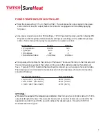
Page 7: ... for the start up of the heater The slower the ramp to the final set point the less temperature overshoot the system will incur and other related problems the system will have Typically TUTCO SureHeat heaters should be ramped up over a period of several minutes The following are recommended ramp rates based on final temperature For custom ramp rates consult with factory Set Point Temperature Ramp ...

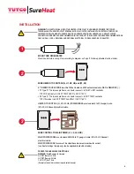
Page 8: ...st be sized based on maximum heater current see heater ratings to properly size by applicable electrical codes MOUNT AND WIRE HEATER Mount heater before wiring Wire according to diagram on Page 9 Follow applicable electrical codes 1 2 3 WARNING THE INLET AIR GAS SIDE OF THE HEATER IS THE PLASTIC HOUSING END WHERE THE POWER TERMINALS AND THERMOCOUPLE TERMINAL BLOCK IS LOCATED INSTALLING THE HEATER ...

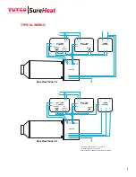
Page 9: ...2 G S1 S1 SureHeat Max 1Ø EXIT TEMP CONTROL AC INLET LIMIT CONTROL HEATER POWER CONTROL TC TC TC TC H1 H2 H3 L1 L2 L3 AC AC ALARM RELAY DC OUTPUT S2 S2 H3 H2 H1 G S1 S1 SureHeat Max 3Ø RELAY Exit Temp Alarm Relay to open at 1405ºF Inlet Limit Relay to open at 300ºF Other settings may damage heater and void warranty SureHeat Max Heater Installation ...

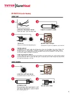
Page 10: ...ersonnel TURN OFF AIR TO SYSTEM 5 CONTROL AIRFLOW During operation with constant airflow the exit temperature will vary only a few degrees from set point Although the heater will not burn out with zero airflow if the heater is operated in a vertical downward position and an airflow of 12 SCFM or less is run through the heater the inlet temperature of the heater will exceed 300 F 150 C and the low ...

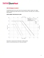
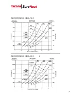
Page 11: ...at different airflows and voltages Pressure readings longer dashed lines are measured at the inlet to the heater with no entrance or exit restrictions MAX MAXIMUM PERFORMANCE CURVE Temperature measured by the internal S2 K thermocouple Minimum recommended airflow is 12 SCFM 340 SLPM ...

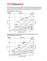
Page 12: ...ife operating conditions leading to premature burnout With a known flow or pressure at the heater entrance follow the flow or pres sure line across until it meets the desired temperature curve Drop a line straight down to intersect the x axis This point along the Heater volts true RMS axis represents the voltage required to generate the desired exit air temperature ...

Page 13: ...13 Q MAX PERFORMANCE CURVE 18kW MAX PERFORMANCE CURVE 36kW ...

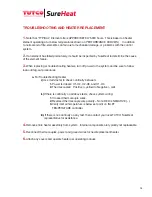
Page 14: ...ocedures a For Troubleshooting Heater i Use multi meter to check continuity between 1 Power terminals H1 H2 H2 H3 and H1 H3 2 Thermocouples Positive yellow to Negative red ii If there is continuity on all above tests check system wiring 1 Crossed thermocouple wires 2 Reversed thermocouple wire polarity Note RED is NEGATIVE 3 Verify inlet air temperature is below set point on INLET TEMPERATURE cont...

Page 15: ...N LIEU OF ALL OTHER WARRANTIES EXPRESS OR IMPLIED INCLUDING WITHOUT LIMITATION ANY IMPLIED WARRANTY OF FITNESS FOR A PARTICULAR PURPOSE OR OF MERCHANTABILITY The information contained in this manual is based on data considered to be true and accurate Reasonable precautions for accuracy has been taken in the preparation of this manual however TUTCO SureHeat assumes no responsibility for any omissio...

Page 16: ...pplied in this operating manual are subject to change without prior notice Contact TUTCO SureHeat for additional assistance 800 258 8290 support tutcosureheat com orders tutcosureheat com 22 Industrial Drive Exeter NH 03833 USA Aerospace Automotive 3D Printing Electronics Medicine Packaging Printing Platics Textiles ...

Reviews: