


Advanced Controls
3 - 4 Video Driver Controls
3
Display Properties
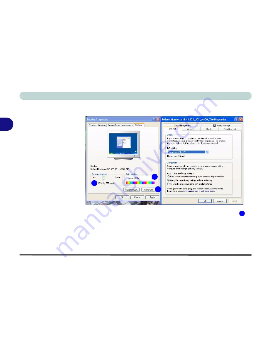
When the
Display Properties
control panel is open, click the
Advanced
(button) to bring up the options tabs. Clicking through these tabs allows you
to make any video adjustments you require.
Figure 3 - 2
Advanced Display
Properties
1
2
3
3
Summary of Contents for Slider D400S
Page 1: ......
Page 2: ......
Page 42: ...Introduction 1 22 1...
Page 110: ...Drivers Utilities 4 16 4...
Page 182: ...A 6 A...


