1 3/8”
3/4”
1 1/4”
4”
2 3/4
4”
1 3/8”
1 3/8”
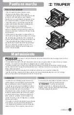
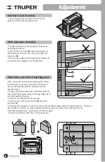
Misaligned Extension
Properly Aligned Extension
8
Anti-chip Guard Assembly
• The anti-chip guard is mounted in the rear of the
planer and is fixed with the butterfly nuts.
Adjustments
• The table extensions are factory aligned, however, can
be misaligned with use.
• Adjust the two hex screws (
A
) that act as stoppers for
both extensions (front and rear). Previously, loosen the
safety nuts (
B
).
• Set one straight edge piece through the main table, and
the extension to be adjusted to verify alignment.
Table Extensions Assembly
• Plan a wood piece and measure thickness after cutting.
If the thickness is not even in both sides of the piece, is
because the cutter head and the work piece are not
properly aligned.
• To align, use two identical pieces of hard wood with the
shape and measurements shown in the image (
C
) to level
the cutter head with the table.
• Using care, lean the planer on its rear side.
• Under the main table, loosen the lock (
D
) horizontal
cone gear (
E
).
• Disengage the cone gears and turn the vertical cone gear (
F
) to adjust height in the appropriate side. Turning the
gear one step of a tooth in a counter clockwise direction equals an increase of 0,05” planning thickness.
• After making adjustments, couple and secure the cone gears.
• If necessary, repeat the procedure in the opposite side.
Work Table and Cutter Head Alignment
A
D
B
C
C
F
E
135°
125°
ENGLISH
Summary of Contents for 16240
Page 13: ...13 Notas ESPA OL...
Page 14: ...Notas 14 ESPA OL...
Page 29: ...13 Notes ENGLISH...
Page 30: ...Notes 14 ENGLISH...


