background image


 True Blue Power 


Revision 1, June 15, 2018


3      


1.2.4 Versions 


Non Lighted 


Lighted 


Power Input 

Location 


USB Connector 


M6430202-1  

M6430202-11


Rear  

Dual: Type A+Type C  

M6430202-2  

M6430202-12


Bottom  

M6430202-3  

M6430202-13


Rear  

Dual: Type C+Type C  

M6430202-4  

M6430202-14


Bottom  

M6430202-5  

M6430202-15


Rear  

Dual: Type A+Type A  

M6430202-6  

M6430202-16


Bottom  

M6430202-7


M6430202-17


Rear  

Single: Type C  

M6430202-8


M6430202-18


Bottom  

M6430202-9


M6430202-19


Rear  

Single: Type A  

M6430202-10


M6430202-20


Bottom  


Table 1.4 


SECTION 2 PRE-INSTALLATION CONSIDERATIONS  


2.1  

COOLING 


No external cooling is required. The unit will become warm when in use. This is normal and within 

operational parameters. No special mounting considerations are required; however, mounting to a metal 
surface can help dissipate any heat generated and extend the life of the product.   


2.2  

EQUIPMENT LOCATION


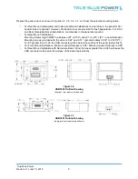
The USBT202 High Power USB Charging Port is designed for mounting flexibility, allowing for installation 

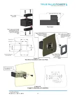
in the cockpit or in the cabin. It is designed for panel mounting and can be installed in a rectangular 
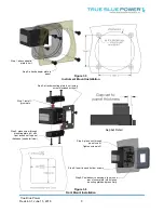
configuration or, with an available installation kit, can be front mounted with a cosmetic cover plate. An 
instrument mounting adapter bracket is also available to easily mount the unit in a standard 2.25 inch 
round instrument opening that may already exist in the cockpit panel. There are two versions to choose 
from which allow the input connector to be located either on the rear of the unit or from the bottom.   
  

The unit can be mounted in any orientation. Clearance should be provided for the mating connector which 

may require an additional inch beyond the rear of the unit.   


2.3  

ROUTING OF CABLES


Avoid sharp bends in cabling and routing near control cables. Avoid close proximity and contact with 

vehicle structures, equipment or other obstructions that could chafe wires during operation and cause 
undesirable effects.  


2.4  

LIMITATIONS  


The USB Type-C interface is an exciting new connector for electronic devices. Beyond the physical format 

of the Type-C connector, it also allows for a variety of interface options when communicating with 
compatible devices. This device-to-charger communication is defined within the USB 3.1 Specification and 
Power Delivery 2.0 standards. However, manufacturers of consumer electronic devices and/or cables may 

Summary of Contents for USBT202 Series

Page 1: ...ng Port True Blue Power a division of Mid Continent Instrument Co Inc Mid Continent Instrument Co Inc dba Mid Continent Instruments and Avionics 9400 E 34th Street N Wichita KS 67226 PH 800 821 1212 FX 316 630 0723 Revision 1 June 15 2018 Copyright 2018 Mid Continent Instrument Co Inc ...

Page 2: ...e and operate As a high power DCP the USBT202 can provide up to 3 0 amps of power to charge USB devices including the higher demand products Most dual USB chargers typically provide 1 0 amp on one port and 2 1 amps on the second port but the USBT202 can provide 3 0 amps to both ports simultaneously for dual port units The unit has built in protections for short circuit over current and low voltage...

Page 3: ...rectangular configuration or with an available installation kit can be front mounted with a cosmetic cover plate An instrument mounting adapter bracket is also available to easily mount the unit in a standard 2 25 inch round instrument opening that may already exist in the cockpit panel There are two versions to choose from which allow the input connector to be located either on the rear of the un...

Page 4: ... contains interconnect diagrams mounting dimensions and other information pertaining to the installation of the USBT202 Single and Dual USB Charger After installation of cabling and before installation of the equipment ensure that power and ground are applied to the proper pins specified in Section 3 3 2 Pin Assignment Information 3 2 UNPACKING AND INSPECTING EQUIPMENT When unpacking this equipmen...

Page 5: ... 3 2 Pin Assignment Information INPUT POWER Pin A keyed Positive DC input 10 to 32 VDC power Pin B Negative DC input ground 3 3 3 Harness Verification Note The USBT202 has built in reverse polarity protection for the power connector If Pins A and B are swapped the unit will not be damaged but will also not function Once the cable harness is prepared prior to connecting the USBT202 activate the sys...

Page 6: ...screws length MUST be between PT 0 150 and PT 0 210 PT panel thickness Mounting screws provided with the unit are 0 24 and 0 31 accommodates 0 030 to 0 160 PT For PT greater than 0 125 the USB connector will be below the surface of the panel below flush For Front Mount Installations Minimum panel thickness is 0 04 Maximum panel thickness is 0 20 For Rear Mount Installation with Decorative Bezel Pa...

Page 7: ...r to prevent accidental damage to other systems it is not recommended to attach the output to other equipment prior to verification Verify the output of the unit at the terminating end of the cable with a multimeter to ensure proper voltage and polarity Once verified installation can be completed and functionality should be checked Figure 3 4 Rear Mount Installation Panel Cutout Detail ...

Page 8: ...il view Step 3 attach mounting plate to unit using screws included with unit Step 4 place unit through panel cutout Tighten screws x2 Step 6 Peel adhesive backing align pins on rear of cover plate into holes on mounting plate and press firmly Step 5 Insert top and bottom screws Gap Set Detail Step 1 attach adapte r plate to unit Step 2 attach adapter plate to panel Figure 3 6 Front Mount Installat...

Page 9: ...True Blue Power Revision 1 June 15 2018 9 Single Port Rear Mount Installation Port protrusion toward top Figure 3 8 ...

Page 10: ...ature returns to a safe level the USBT202 will automatically reestablish the higher charge current level with the device and continue charging 4 2 PROTECTIVE FEATURES 4 2 1 Short Circuit Protection The USBT202 is capable of surviving a short circuit event without permanent damage The unit goes into an over current condition so that the average current is significantly reduced and the device is pro...

Reviews: