


19
S
ection
5 — S
ervice
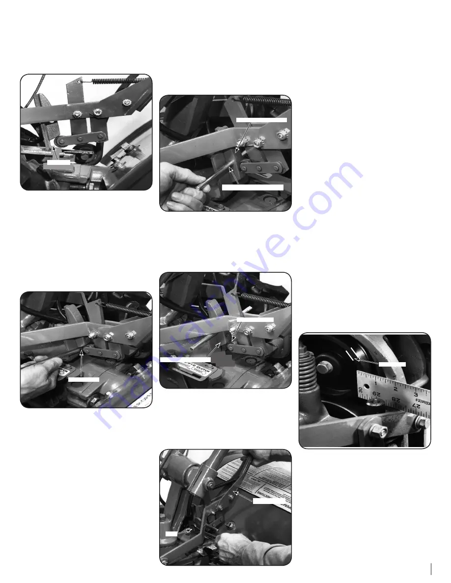
2.
Move the Wheels/Tines/PTO Drive Lever fully
down to the FORWARD position. The clutch
roller at the bottom of the lever should be
positioned underneath the belt adjustment
block. See Figure 5-13. Don’t let the clutch
roller move during the next few steps. If it
moves, you’ll get a false belt tension reading.
1⁄4” - 5⁄16”
Figure 5-13
3.
The belt tension is correct if the front of the
clutch roller is 1⁄4”-to-5⁄16” away from the face of
the upright bracket that holds the adjustment
block in place. See Figure 5-13. To measure this
distance:
a.
Without moving the clutch roller, try
inserting the 1⁄4”-thick, slotted end of
the belt adjustment tool in between
the roller and the upright bracket. The
flat edge of the tool must be facing the
roller. See Figure 5-14.
Slotted End
Figure 5-14
b.
If only the slotted portion of the tool
will fit, the belt tension is correct.
c.
If the slotted part of the tool will not fit
in, the belt is too loose.
d.
If the full thickness (5⁄16”) of the tool
easily fits in, the belt is too tight.
4.
If the belt tension is correct, move the Wheels/
Tines/PTO Drive Lever back to NEUTRAL.
How to Adjust the Belt Tension
1.
As described in the following steps, the drive belt
tension is adjusted by moving the adjustment
block up or down. Moving it down will tighten
the belt; moving it up loosens the belt.
NOTE:
The distance the block moves
approximately equals the distance the roller
moves. In most cases, the clutch roller will
not have been very far out of position, so the
adjustment block will only need to be moved
slightly (up or down).
2.
Move the Wheels/Tines/PTO Drive Lever
to NEUTRAL position. The clutch roller will
come to rest anywhere on the face of the belt
adjustment block, depending upon drive belt
length and current belt tension adjustment.
3.
Insert the belt adjustment tool through the
hole in the side of the adjustment block,
spacing the ends of the tool equally on both
sides. See Figure 5-15. Rotate the tool so the
slotted end faces down.
Adjustment Block
Belt Adjustment Tool
Figure 5-15
4.
Place the Wheels/Tines/PTO Drive Lever in
FORWARD position. The arms of the clutch
control yoke will be resting on the belt
adjustment tool and the clutch roller should
be engaged slightly beneath the adjustment
block. See Figure 5-16.
Clutch Roller
Adjustment Block
Figure 5-16
5.
Use one hand to hold the drive lever in
FORWARD while using a 9⁄16” wrench to loosen
— don’t remove — the bolt at the back of
the belt adjustment block. See Figure 5-17.
The adjustment block should be free to move
either up or down.
Bolt
Drive Lever
Figure 5-17
6.
Push the drive lever down if the belt needs
tightening. Pull the lever up if the belt needs
to be loosened. Hold the drive lever in place
and tighten the bolt in the adjustment block
firmly.
7.
Let go of the drive lever and remove the
belt adjustment tool from the hole in the
adjustment block.
8.
Check the tension on the belt by following the
previous instructions “How to Measure Belt
Tension.”
NOTE:
If the adjustment block is all the way
down and the measurement between the
clutch roller and the bracket is less than 1⁄4”,
then a new drive belt is needed.
Reverse Drive System
These instructions explain how to inspect and adjust
the various reverse drive components.
But first, here’s how the reverse drive system works.
When you raise the Wheels/Tines/PTO Drive Lever
up in REVERSE position, this lowers the rubberized
reverse disc — it’s attached to the engine drive
pulley — until this rotating disc contacts the
transmission drive pulley. The friction between the
rotating reverse disc and the transmission pulley
causes the transmission drive shaft to be powered
in a counterclockwise direction — as viewed from
the operator’s position behind handlebars. The
drive shaft then turns the wheels and tine shafts in a
reverse direction.
The reverse disc is made of steel with a special, long-
lasting rubber compound bonded to the disc rim.
Since this is a wearing part, it should be inspected
after every 30 operating hours.
1.
Measure the width of the outside edge of the
disc as shown in Figure 5-18. Replace the disc
before the rubber edge wears to a thickness
of 1⁄8” or less. Failure to do so could cause the
steel underneath the rubber to damage the
transmission pulley.
Disc Edge
Figure 5-18
2.
Look for big cracks or missing chunks of
rubber from the disc. If so damaged, the disc
should be replaced immediately. See the
Service section of this manual for instructions
on replacing the disc.
NOTE:
Extend the life of the reverse disc by
always pausing in NEUTRAL before shifting
between FORWARD and REVERSE. Also, the
reverse disc is not suited for continuous or
sustained reverse operation. Use reverse
sparingly.


