background image

7

Operating manual

TROX air terminal units

Type VFC volume flow controllers 

1

2

3

4

y

VFC

~

~

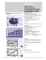
Continuous control input signal

Variable volume flow rate wiring

E03

24 V

Room temperature 

controller

Actual value 

output (value to 

be set)

1

2

3

VFC

~

S1

E01, E02

24 V / 230 VAC

1

2

0

3

~

VFC

2

S2

3

2-wire control 

min

 / 

max

24 V / 230 VAC

E01, E02

Danger!

Danger of electric shock! Do not touch any live 

components!  Electrical equipment carries 


a dangerous electrical voltage.

• 

Only skilled qualified electricians are allowed 


to work on the electrical system.

• 

Switch off the power supply before working on 

any electrical equipment. 

Actuator E01, E02

Electrical connection data:

E01: 

24 V AC  ±20%   50/60 Hz;   

4 VA


24 V DC  ±20%    


2,5 W

E02: 

230 V AC  

50/60 Hz  

4 VA

Switches provided by the customer (volt-free contacts) can 

be used for making the switching procedures shown below:

1-wire control (illustration above)

Switch S1 open : 

min

Switch S1 closed 

: 

max

2-wire control (3-point) (illustration in middle)

Switch S2 at 0:  Drive stopped
Switch S2 at 2:  

min

Switch S2 at 3:  

max

Actuator E03

Electrical connection data:

Supply:  24 V AC  ±20%  50/60 Hz  

4 VA


24 V DC  ±20%   


2,5 W

Control signal:   

0-10 V DC 

Ra > 100 kohm

Actual value output:  

0-10 V DC

Room temperature control

A dedicated room temperature controller or a DDC outstation 

with 0-10 V DC output is connected with at least 2 wires 


(terminals 1 and 3) as shown in the circuit diagram. If the 

controllers are on the same supply voltage (24 V) make sure 

that terminal 1 of the VFC is identical to the ground of the 

control signal.

Note:


Override control 

max

 with 24 V DC at terminal 3.

1-wire control 

min

 / 

max

min

 - 

max

 switching wiring

                 ~

    -            +

   N            L

                       ~

    -                  +

   N                  L

-       +

Actuator E01 ... E03

Summary of Contents for VFC series

Page 1: ...wiring____________________7 min max switching operation actuator with mechanical stops___________________________8 min max switching wiring______________________9 min max switching setting___________...

Page 2: ...must be taken into account during the design stage Use of VFC series volume flow controller in aircraft is not permitted In systems with aggressive air only air terminal units made of plastic should b...

Page 3: ...site using the rotary knob Factory setting 5 Actuator E01 E02 E03 For variable airflow rate or min max switching Volume flow rate is set on potentiometers Shut off down to leakage airflow is possible...

Page 4: ...and acoustic effects Horizontal or vertical installation in combination with volume flow rate measuring unit VMR arrange the sensor tubes at 45 offset from the controller axis Installation behind a be...

Page 5: ...7 8 9 10 3 4 5 6 7 8 9 10 80 6 7 10 14 19 25 33 42 20 26 35 49 68 91 119 150 100 6 10 15 22 30 40 50 65 22 36 54 79 108 144 180 234 125 11 15 22 30 44 60 78 100 40 54 79 108 160 215 280 360 160 18 31...

Page 6: ...manently on Position set Flashing once a second Actuator operating Flashing twice a second Actuator is jammed and stationary Off No supply voltage Actuator E03 The relationships between the setting va...

Page 7: ...A Switches provided by the customer volt free contacts can be used for making the switching procedures shown below 1 wire control illustration above Switch S1 open min Switch S1 closed max 2 wire cont...

Page 8: ...gnet is integrated in the removable position indicator Make the corresponding settings on the mechanical stops Deactivate gearbox disengagement again and reconnect the position indicator see also page...

Page 9: ...onnection data M01 24 V AC 20 50 60 Hz 1 VA 24 V DC 20 0 5 W M02 230 V AC 50 60 Hz 3 VA Switches provided by the customer volt free contacts can be used for making the switching procedures shown below...

Page 10: ...the reverse Place the magnet on the point indicated with magnetic gear release The gearbox is now disengaged and the actuator can be moved min max switching setting Remove the mechanical limiters Set...

Page 11: ...crew and move the rotary knob to position 5 The actuator is simply pushed on and it engages in the mounting bracket Order code for expansion sets see page 1 Fixing screw Setting 5 Mounting the actuato...

Page 12: ...ry to remove the locking screw and move the rotary knob to position 5 Order code for expansion sets see page 1 Locking screw Coupling Rotary knob 1 2 Perform the following steps to mount the actuator...

Reviews: