2
Operating manual
TROX air terminal units
Type VFC volume flow controllers
VFC
Area of application
TROX VFC series volume flow controllers are mechanical
system-powered controllers for controlling the airflow in
constant and variable air volume systems.
3 variants of the volume flow controllers are available:
•
Constant volume flow rate
•
min
-
max
switching
Actuator with potentiometers (type E01, E02)
Actuator with mechanical stops (type M01, M02)
•
Variable volume flow rate,
Actuator with potentiometers (type E03)
The set flow rate must always be set by the customer on site.
The setting is made without adjustment devices.
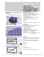
Each volume flow controller has a sticker with a characteristic
for determining the volume flow rate. One or two settings
are read off and transferred to the rotary knob or actuator
(potentiometer or mechanical stops).
Operating modes
•
Constant volume flow rate
The volume flow controller keeps the set flow rate constant
independently of the duct pressure.
•
Variable volume flow rate
The volume flow controller keeps a variable set flow rate
constant independently of the duct pressure. For this
purpose, the volume flow controller receives a control
variable from a room temperature controller or air quality
controller, a set point adjuster or a DDC outstation. The
control variable is a 0 to 10 V DC voltage signal.
•
min
-
max
switching
The volume flow controller works with two
setpoint values
that are switched over using switches or relays provided by
the customer.
General information
Correct use
The volume flow controllers are suitable for use in ventilation
and air conditioning systems. Particular conditions can
restrict the functioning capacity and must be taken into
account during the design stage:
•
Use of VFC series volume flow controller in aircraft is not
permitted.
•
In systems with aggressive air, only air terminal units made
of plastic should be used, subject to extensive tests for
suitability.
• Galvanised sheet steel units must not be installed in
contaminated environments (e.g. acetic acid).
• The controller and actuator do not contain any parts that
can be exchanged or repaired by the user.
• The actuator contains electronic components therefore
must be separated from domestic waste. When disposed
of, local up to date regulations must be complied with.
•
The mechanical components of VFC series volume flow
controllers are maintenance-free.
•
Sticky constituents of the air, in particular in association
with fluff, can lead to impairment or failure of the regulation
function.
Safety notes
Danger!
Danger of electric shock! Do not touch any live
components! Electrical equipment carries a
dangerous electrical voltage.
•
Only skilled qualified electricians are allowed to
work on the electrical system.
•
Switch off the power supply before working on
any electrical equipment.
• Safety transformers must be used.
• Installation should only be carried out by specialists.
The normal rules of site working, in particular the health
and safety regulations must be complied with.
•
For installation, wiring, and commissioning observe
the recognised technical regulations, especially safety
and accident prevention regulations.
•
Due to the danger of injury on edges and burrs, transport
and installation may only be performed while wearing
gloves.
•
Install the units proficiently with suspension points
and secure with locknuts. Only load the suspension points
with the units' own weight. Adjacent components and
connecting ducts must be supported separately.
•
Only use units with ATEX approval for rooms containing
a potentially explosive atmosphere.


