background image

Installation manual for automatic extract air valve

8

On-site precautions

7.  Electrical installation

Electrical connection

The automatic extract air valve works with an electro-thermal 
actuator, which has to be connected with a 2-pin cable to 
230V/50Hz.

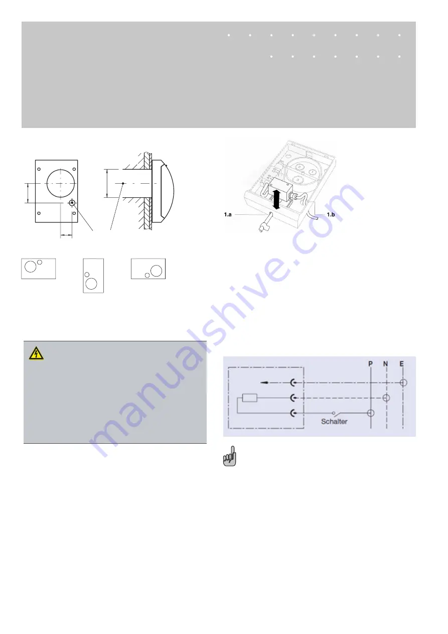
1.a For surface mounting: open the cable feed-through with 
pliers.
1.b For flush mounting: feed the cable through this opening.
2.   Loosen the electrical socket.
3.   Loosen the grommet nut from the electrical socket.
4.   Pull the cable through the grommet nut, then screw this 
back into
      the electrical socket.
5.   Connect the cable to the luster terminal.
6.   Screw the electrical socket back on again.

It must be possible to disconnect the unit from the mains after 
installation, unless the unit is equipped with a switch to 24.3. 
This can be done by making the plug accessible or by fitting a 
switch into the fixed installation in compliance with the installa-
tion regulations.

Connection diagram

P = Phase

N = Neutral

E = Earth


Note

The automatic extract air valve can be controlled with a separate 

switch or coupled with the light switch.

75

44

2

1

Ø 100

1

 Recess for HFA connection in frame wall

2

  The position of the hole for the cable penetration de-

pends  


on the installation orientation of the 


GEFAHR!

Stromschlag beim Berühren spannungsführender 
Teile. Elektrische Ausrüstungen stehen unter 
gefährlicher elektrischer Spannung. 
Nichtbeachtung kann Tod, schwere Körperschäden 
oder Sachschaden verursachen!

–  An den elektrischen Komponenten dürfen nur 
 

Elektrofachkräfte arbeiten.

–  Vor Arbeiten an der Elektrik die Versorgungs-
 

spannung ausschalten.

Summary of Contents for HESCO HFA

Page 1: ...Installation manual Automatic extract air valve Type HFA Subject to change All rights reserved L 50 6 01e ...

Page 2: ...HFA 9 9 Maintenance 10 Maintenance and cleaning 10 1 General information This installation manual describes the automatic extract air valve type HFA To ensure correct functioning of the automatic extract air valve it is essential to read the provided installation manual before starting any work and to comply with it The manufacturer does not accept any liability for any malfunction or damage resul...

Page 3: ...erden in Ex Bereichen im Freien ohne ausreichenden Schutz gegen Witterungseinflüsse in Atmosphären die planmässig oder ausserplan mässig aufgrund chemischer Reaktionen eine schädigende und oder Korrosion verursachende Wirkung auf das Produkt ausüben WARNUNG Verletzungsgefahr bei unzureichender Qualifikation Unsachgemässer Umgang kann zu erheblichen Personen und Sachschäden führen Alle Tätigkeiten ...

Page 4: ...ing knowledge and actual experience to enable them to carry out their assigned duties understand any potential hazards related to the work under consideration and recognise and avoid any risks involved Limitation of liability The information in this manual has been compiled with refe rence to the applicable standards and guidelines the state of the art and our expertise and experience of many year...

Page 5: ...e transported to the installation location in their original packaging Use only lifting and transport gear designed for the required load Always secure the load against tipping and falling Cumbersome equipment should be transported with at least two people to prevent injury and damage Storage Please note Store the product only in its original packaging Protect the product from the effects of weath...

Page 6: ...epending on the building heating energy can be reduced by 10 30 in terms of total consumption The heating system can be designed to smaller dimensions The automatic extract air valve HFA is suitable for use in all buildings with central extract air systems The automatic extract air valve HFA works with two volume flow rates Basic volume flow rate can be selected Required volume flow rate can be se...

Page 7: ...3 Snap fastener 4 Cable penetration for flush mounting 5 Cable feed through for surface mounting 6 Electrical socket 7 Fixing holes Ø10 8 Junction box 9 Electro thermal actuator 10 Damper with volume flow rate plugs 11 4 plastic dowels Nr 5 x 25 12 4 washers Ø4 3 x 14 13 4 cross head screws Ø3 5 x 32 Installation Opening the cover Press the snap fastener and lift the cover out of the main housing ...

Page 8: ... the mains after installation unless the unit is equipped with a switch to 24 3 This can be done by making the plug accessible or by fitting a switch into the fixed installation in compliance with the installa tion regulations Connection diagram P Phase N Neutral E Earth Note The automatic extract air valve can be controlled with a separate switch or coupled with the light switch 75 44 2 1 Ø 100 1...

Page 9: ...l p s Pa Grundvolumenstrom o Volumenstrom m h 0 1 2 3 4 50 dB A 45 dB A 40 dB A 35 dB A 30 dB A 400 300 200 100 80 60 50 40 30 20 6 8 10 20 30 50 100 150 LwA HFA 200 ps Perte de charge statique p s Pa Débit d air de base o Débit d air m h 0 1 2 3 4 50 dB A 45 dB A 40 dB A 35 dB A 30 dB A 400 300 200 100 80 60 50 40 30 20 6 8 10 20 30 50 100 150 LwA HFA 200 ps p s Pa Base air volumen rate o 0 1 2 3...

Page 10: ... die Versorgungs spannung ausschalten Maintenance and cleaning Please note Clean surfaces with a damp cloth Only use commercially available non corrosive cleaning agents Do not use cleaning agents that contain chlorine The use of cleaning tools for removing persistent contamination e g scrubbing sponges and scouring agents can damage the surface and is not permitted Contaminated filter elements ne...

Reviews: