background image

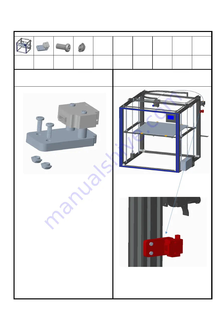
Step 16: assemble the filament run out detector

detector

1pcs

screws

PM4*12

2pcs

boat nuts

M4 2pcs

1. Take the boat nut M4, screw PM4*12, as shown in the figure,
align with the switch assembly, and screw in the boat nut M4.

2. Fix the switch assembly with boat nut M4 and screw PM4*12 on
the aluminum profile at the lower end of the feeder, as shown in
the figure, the arrow direction is upward.


3d printer

1set

Assemble material specification and quantity:

Summary of Contents for X5SA-500

Page 1: ...X5SA 500 Installation instructions SHENZHEN TRONXY TECHNOLOG CO LTD ...

Page 2: ...the screw PM5 45 through the sinking hole of aluminum profile 2 screw in the tooth hole of aluminum profile 3 align the edge of aluminum profile and lock the screw Take the Angle code assembly align and sink the ship s screws with the aluminum profile groove and fasten them on the aluminum profile with screws 1 Product assembly 1 Take 1 Angle code 2 washers and 2 screws PM4 8 assemble them in the ...

Page 3: ...d 2 pieces of aluminum profile 4 and place them according to the position shown The hole in the middle of aluminum profile 4 is on the inner side the sunk hole is below and the frame aluminum profile 1 is on the upper and outer side Align the sides of aluminum profiles and lock them together with 6 sets of corner codes Step 2 frame assembly Assemble material specification and quantity Aluminum4 th...

Page 4: ... 3 install the sliding plate left sliding plate component 1pcs underframe 1pcs 2 Put the end of aluminum profile 2 of the bottom frame component into L Angle code as shown in the figure Screw on the M5 5 meter do not lock tightly to facilitate subsequent adjustment left sliding plate component right sliding plate component 1 Take 5 2 aluminum profiles and insert the left and right components of th...

Page 5: ...d plate with the drag end hole as shown in the figure through with 2 PM3 8 screws and tighten with 2 M3 nuts Place the aluminum profile 6 on the left and right sliding plate use 2 PM4 8 screws through the drag chain riser screw on 2 boat nut M4 go through the aluminum profile groove lock the screw PM4 8 4 As shown Install aluminum6 and left right sliding plate parts together with 4pcs screws PM4 1...

Page 6: ...on the aluminum profile with boat nut M4 according to the position shown Align the edge 2 As shown in the figure take the right cross wheel assembly use three screws of PM4 8 three boat nuts align the positions and screw on three boat nuts M4 Also assemble 1 left wheel block Step 5 installation of XY axis motor and wheel Assemble material specification and quantity underframe 1pcs left wheel compo...

Page 7: ...do not force too much and lock the screw Tie 4pcs Diagram of tie belt mainframe 1pcs belt 2pcs Assemble material specification and quantity Step 6 belt assembly 2 Move the belt through as shown wrap the motor gear on the rack surface and determine the belt trend Press the slide plate against the motor bottom plate and fasten it with the tie belt at the lower end of the sheet metal groove of the pr...

Page 8: ... Z axis insert 2 screws PM4 8 as shown in the figure put 2 M4 spring pads on and screw 2 boat nuts M4 Assembly 2 sets screws PM4 8 24pcs Step 7 assemble linear bearing and z axis motor boat nut 8pcs screws PM3 8 8pcs Assemble material specification and quantity feed screw nut 2pcs Z axis motor component 2pcs diaphragm 2pcs LMK 4pcs bearing block 2pcs 2 Take 1 piece of bearing block insert 2 screws...

Page 9: ...at step 2 to assemble another z axis slide carriage as shown in the figure 2 Adjust the ship nut of the black iron plate of the z axis sliding rack put the z axis sliding rack into the aluminum profile 2 in the position shown and the hole of M3 is on the inner side Align the polished rod with the hole of the upper and lower aluminum profile and use the screw of PM4 20 to pass through the hole of t...

Page 10: ... and boat nut M4 on the feeding motor components boat nuts M4 2pcs screws PM4 6 2pcs Assemble material specification and quantity mainframe 1pcs feed motor component 1pcs 1 Assemble the feeding motor components as shown in the picture with 2 PM4 6 screws and boat nut M4 Step 9 feed motor installation ...

Page 11: ...hot bed components to the side plates with 8 PM4 12 screws as shown in the figure The drag chain bracket is close to the side of the feeding motor component Rotate the screw rod in the same direction to make the platform move up and down synchronously and make sure the movement is flexible Otherwise loosen the screw PM4 12 and adjust the screw at the both end of the polished rod nuts M3 8pcs screw...

Page 12: ...ox assembly this step can be installed after wiring 1 Take 1 piece of the control box and take 4 screws and boat nut Assemble them according to the position shown 2 Align the side of the control box with the aluminum profile of the mainframe as shown in the figure and lock it in the groove of the aluminum profile with the boat nut ...

Page 13: ... the power supply voltage in the region Adjust the gear with one word screwdriver Select 220V and slide the gear into 220V as shown in the figure Select 110V and slide the shift to 110V 2 Fix the aluminum profile groove with boat nut and lock the 4 screws PM4 8 as shown in the figure mainframe 1pcs Assemble material specification and quantity ...

Page 14: ...crews PM4 6 as shown in the figure hang the material plate on the screw rod screws PM4 6 2pcs Assemble material specification and quantity 3d printer 1set 1 Pick 1 piece material rack plate 2 screwsPM4 6 2 boat nut M4 assemble as shown boat nuts M4 2pcs material rack 1pcs Step 13 assemble the rack ...

Page 15: ...rm sticker on the heatbed 1 Pull the feeding tube into the air nozzle hole of the feeding component press down the plastic outer ring of the air nozzle insert the feeding tube loosen the plastic ring and jam the feeding tube as shown in the figure Make sure the material tube is jammed Then put the other end of the feeding tube into the air nozzle of the printing head assembly and confirm that the ...

Page 16: ...seat is aligned with the end face of aluminum profile 4 and lock the 2 screws PM4 8 as shown in the figure Edge alignment 1 Put 2pcs screw PM4 8 through Y switch component then lock with T nut M4 same as illustration boat nuts M4 2pcs 3d printer 1pcs Y Switch 1pcs Assemble material specification and quantity Step 15 limit switch assembly ...

Page 17: ...crew PM4 12 as shown in the figure align with the switch assembly and screw in the boat nut M4 2 Fix the switch assembly with boat nut M4 and screw PM4 12 on the aluminum profile at the lower end of the feeder as shown in the figure the arrow direction is upward 3d printer 1set Assemble material specification and quantity ...

Page 18: ...oot cup 4pcs Step 17 strengthen rods and chains assembly Assemble material specification and quantity 3d printer 1pcs boat nuts M4 8pcs screws PM4 16 4pcs screws PM4 12 4pcs chains base 2pcs Drag chain 1pcs 2 Fix the strengthen rods assembly on the aluminum profile with boat nut M4 and screw PM4 16 as shown in the figure 1 Take 1 strengthen rods 2 boat nuts and 2 screws PM4 16 and screw in the sti...

Page 19: ...TEMP ZSTOP HOTBED Power X Motor Y Motor Z1 Motor Z2 Motor E Motor YSTOP FSTOP Printing head Step 18 wiring Z1 motor Z2 motor Y Motor X Motor E motor Heat bed Printing head The host box Power YSTOP FSTOP ...

Page 20: ...X5SA 500 Physical wiring diagram F STOP ...

Page 21: ...k menu and return to the superior menu 2 2 click the machine information and display the following figure display the machine brand ID version and other information Click back menu to return to the superior menu 2 3 click the menu to enter Chinese and English Click back menu to return to the superior menu 2 Touch screen operation guide 2 1 click the state and display as shown in the figure display...

Page 22: ...m Click the icon and the machine returns to the origin icon back to superior menu 2 4 click factory Settings to ask whether the factory Settings are restored Click to return to restart and restore the factory Settings 2 5 click the screen correction icon to enter the screen correction and click the cross position for correction Adjust the screen when the menu is off save it back 3 Click the tools ...

Page 23: ...Remove the consumables to warm up before pulling them out Set the heating temperature the temperature reached click the icon to return the material When installing the filaments make the filaments go straight out into the hole of the filament run out detector and press down the feeder s pressing block as shown in the figure Pass the filaments through the feeder to the filaments pipe and then click...

Page 24: ...e X icon stop machine extrusion head moves to set position please loosen the adjusting nut release the spring rebound let between nozzle and hot bed in the thickness of a piece of A4 paper A4 paper between the nozzle and the platform moving a sense of resistance but will not cut paper Please adjust the four points circled in A4 paper thickness 3 5 click the fan icon to enter the fan setting and tu...

Page 25: ...nting The number beside the pointer icon shows the printing speed and the percentage shows the printing progress 4 2 1 click the icon to stop printing and ask whether to replace the consumables To replace the consumables click YES the consumables in step 3 3 and return to continue printing Click no and go back to print 3 7 click the Z offset icon to enter the Z axis position adjustment The functio...

Page 26: ...ange The initial parameters are set by slicing software The parameters can be changed in printing as shown in the figure corresponding to the icon parameters Click the parameters on the right side of the icon enter the parameter setting screen set the parameters click the icon to save and exit and click the icon to exit without saving 5 Filament run out detector when the machine is working the con...

Page 27: ... through pipe If the feeding pipe is not inserted in it is easy to cause the pipe blocking material The pipe should be removed and cleaned 3 Poor quality filaments lead to poor feeding filaments replace high quality filaments after removing the 4 Problems such as not reading the card and online failure a The SD card can be read on the computer but cannot be displayed on the machine format the SD c...

Reviews: