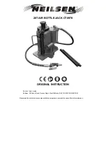
5 Ton (4.5 Metric Ton) Single Stage Jack
Models: 02-7856-0100 (Standard)
02A7856-0100 (with Air Pump Option)
02B7856-0100 (with Air Pump Option & Spring Loaded Casters)
02C7856-0100 (with Spring Loaded Casters)
11/2004 - AA - Rev. 04
- 4 -
5.0 ASSEMBLY
This product is shipped completely assembled and tested and requires no further assembly before
operation. The following sections apply when servicing the unit.
5.1 GENERAL
INSTRUCTIONS
1.
This product should be assembled and/or repaired using good workmanship practices and
proper tools. Bolts and elastic stopnuts should be tightened to a torque not to exceed industry
standards for Grade '5' bolts.
2.
All replacement parts must be the same as or better than the original parts supplied.
3.
Dispose of waste per federal and local laws and regulations.
4.
No modifications are allowed that will adversely affect the jacks safety performance.
5.
The pressure relief valve is not serviceable. It must be replaced as a unit.
5.2 PRE-USE
CHECKS
1.
Refer to the Illustrated Parts List to identify and ensure that all parts are present.
2.
Generally check over unit to assure the tightness of all nuts, bolts and fittings.
3.
With rams completely collapsed, check hydraulic fluid level.
•
Replenish with MIL-H-5606 fluid as required.
•
Fluid Level: 1.5 inches (3.8 cm) below vent.
NOTE:
Refer to fluid manufacturer’s (Appendix) Material Safety Data Sheet, and advisory for
handling and disposal of fluid.
5.3 PERSONNEL
REQUIREMENTS
This jack is to be assembled by qualified technicians familiar with hydraulic systems.
5.4
INSPECTION AND TEST PROCEDURES
1.
Ensure fluid level is within 1.5 inches (3.8 cm) from reservoir vent cap.
2.
Raise ram to full stroke, and check for leaks.
6.0 INSTALLATION
Installation and commissioning requires connection of the air valve to an adequate air supply (Air Pump
equipped Models only).
6.1 AIR SUPPLY REQUIREMENTS
•
25 psi (1.72 bar) Minimum
•
40 psi (2.75 bar) Recommended
•
125 psi (8.60 bar) Maximum
Summary of Contents for 02-7856-0100
Page 2: ......
Page 6: ......
Page 24: ......
Page 25: ...APPENDIX I Hydraulic Schematic...
Page 26: ......
Page 28: ......
Page 29: ...APPENDIX II Haskel Air Pump Technical Specifications Performance Data Drawing 28550...
Page 30: ......
Page 31: ......
Page 32: ......
Page 33: ......
Page 34: ......
Page 35: ...APPENDIX III HC 1753 Hand Pump Parts List...
Page 36: ......
Page 38: ......
Page 42: ......
Page 43: ...APPENDIX IV Material Safety Data Sheet MIL H 5606 Hydraulic Fluid...
Page 44: ......
Page 45: ......
Page 46: ......
Page 47: ......
Page 48: ......
Page 49: ......
Page 50: ......
Page 51: ......
Page 52: ......