USER MANUAL TST40G, V15.01
page
|
1
Technical changes, misprints and errors are reserved.
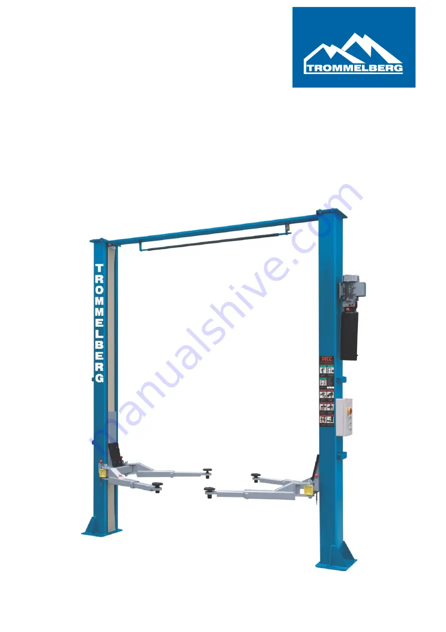
User Manual
4 Ton Two Post Lift Model: TST40G, with upper synchronization
Page 1: ...USER MANUAL TST40G V15 01 page 1 Technical changes misprints and errors are reserved User Manual 4 Ton Two Post Lift Model TST40G with upper synchronization...
Page 2: ...Page 7 3 Installation instructions Page 8 15 3 1 Preparations before installation Page 8 3 2 Precautions for installation Page 8 3 3 Installation Page 9 15 3 4 Items to be checked after installation...
Page 3: ...r whatever bad consequence resulted from improper installation and operation overload running or unqualified ground condition This 2 posts lift is specially designed for lifting motor vehicles that we...
Page 4: ...ommended lifting points Check at any time the parts of the lift to ensure the agility of moving parts and the performance of synchronization Ensure regular maintenance and if anything abnormal occurs...
Page 5: ...gns All the safety warning signs attached on the lift are for the purpose of drawing the user s attention to the safety operation The labels must be kept clean and need to be replaced when they are wo...
Page 6: ...raulic oil to the cylinders and pushes its piston upwards The piston drives the chain to raise the carriage and the lifting arms During the lifting process the safety latch will automatically and firm...
Page 7: ...USER MANUAL TST40G V15 01 page 7 Technical changes misprints and errors are reserved 2 3 Construction of the lift...
Page 8: ...packing list Check the ground conditions of the installation site o The lift should be fixed on a smooth and solid concrete ground with its strength more than 3000PSI 2 1kg mm tolerance of flatness l...
Page 9: ...ce something supporting under the second post and then remove the remaining bolts on the package Step 4 Determine the exact place of installation of the lift o Unpack the posts and decide on which sid...
Page 10: ...hnical changes misprints and errors are reserved Step 6 Installation of the crossbeam o After the columns are erected and aligned mount the crossbeam according to the following drawing Step 7 Mount th...
Page 11: ...hnical changes misprints and errors are reserved Step 8 Install the safety pawls electromagnets and the corresponding protective covers Step 9 Installation of the hydraulic hoses o Connect the oil hos...
Page 12: ...nd o The carriages have to be on exactly the same height o Make sure that the safety pawls are locked to avoid accidents and or injuries o After the cables being fixed adjust and make the cables at bo...
Page 13: ...rs are reserved Step 11 Installation of the control box o Mount the control box on the power side column o Connect the power source according to the wiring diagram page _ Step 12 Installation of the o...
Page 14: ...14 Technical changes misprints and errors are reserved Step 13 Installation of the lifting arms o Connect the lifting arm and the carriage by shafts o Install the lifting arms onto the carriages and...
Page 15: ...o Refer to the operation instructions in advance and keep in mind that no vehicle is on the lift in the process of a trial run o Check and ensure that all the connections are in good condition o NO VE...
Page 16: ...is etc When the lift has raised the vehicle to the desired height switch off the power to prevent any mal operation done by unauthorized people Make sure that the safety lock of the lift is properly l...
Page 17: ...rt for operation Raising Lowering Start Start Press the UP button Press the DOWN button Motor drives the gear pump The lift will first raise a little Cylinder piston drives the chain And then begins t...
Page 18: ...AL TST40G V15 01 page 18 Technical changes misprints and errors are reserved 4 3 Operation instructions IN CASE OF EMERGENCY PRESS THE EMERGENCY STOP BUTTON The main switch also serves as emergency of...
Page 19: ...mmended lifting points and check the correct position of the lifting pads f Keep on raising the vehicle to let it have a bit of clearance from the ground and check again the stability of the vehicle a...
Page 20: ...e motor is blown Replace it The limit switch is damaged or the wire connection is loose Connect it or adjust or replace the limit switch Motor runs but will not raise The motor run in reverse Check th...
Page 21: ...djust it The hydraulic oil is too hot above 45 C Change the oil The seal of the cylinder is abraded Replace the seal Inside surface of the posts is not lubricated well Add lubrication Lowering too slo...
Page 22: ...y 2 steel cable 3 sliders sliding block 4 bolts 5 lifting arm locks 6 lifting arms 7 lifting tray 8 down pulley 6 1 Daily checking items before operation The operator must perform daily checks The dai...
Page 23: ...here is a leakage Check the lubrication and abrasion of the axial pins carriages lifting arms and other related parts Check the lubrication and abrasion of the steel cable Check the expansion bolts an...
Page 24: ...der 1 set 7 Drive oil cylinder 1 set 8 Power unit 1set 9 Base cover plate 1 pc 10 Control box 1set 11 Steel cable 2 pcs 12 Long arm fender 2 pcs 13 Lifting arms bolts 4 pcs Package of accessories incl...
Page 25: ...USER MANUAL TST40G V15 01 page 25 Technical changes misprints and errors are reserved 7 2 Overall diagram...
Page 26: ...served 7 3 Hydraulic working system 1 drive oil cylinder 2 assistant oil cylinder 3 manual unloading valve 4 throttle valve 5 motor 6 coupling 7 gear pump 8 single way valve 9 over flow valve 10 anti...
Page 27: ...USER MANUAL TST40G V15 01 page 27 Technical changes misprints and errors are reserved 7 5 Wiring diagram...
Page 28: ...ical changes misprints and errors are reserved Trommelberg is a trademark of the August Handel GmbH Heinrich Hertz Str 3b D 14532 Kleinmachnow b Berlin Tel 49 0 30 217 333 20 Fax 49 0 30 217 333 19 ww...