background image


Chapter 1 


Before Use 


            page 

1. 1     Installation Requirements


1-  2 


1. 2     Originals Prohibited from Duplication


1-  3 


1. 3     Features


1-  4 


1. 4     Specifications


1-  5 


1. 5     Appearance


1-  7 

   1. 5. 1     Front view  


1-  8 

   1. 5. 2     Rear view 


1-  9 


1. 6     Specifications for the Scan Original


1-10 


1. 7     Specifications for the Printing Paper


1-13 

   1. 7. 1     Papers not available to use 


1-13 

   1. 7. 2     Keeping the paper in the custody  


1-14 

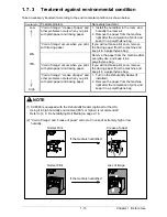
   1. 7. 3     Treatment against environmental condition 


1-15 

Chapter 1   Before Use 

1-1

Summary of Contents for CX 8048

Page 1: ...Instruction Handbook CX 8048 Large Format System ...

Page 2: ... occur Use a separate power line and install the PRINTER as far as possible from said equipment This product meets the ENERGY STAR guidelines for energy efficiency The International ENERGY STAR Office Equipment Program is an international program that promotes energy saving through the penetration of energy efficient computers and other office equipment The program backs the development and dissem...

Page 3: ...t the USER S Manual and have the following meaning WARNING This WARNING mark means that there is a possibility of death or serious injury if you ignore or do not follow the said instruction CAUTION This CAUTION mark means that there is a possibility of injury or physical damage if you ignore or do not follow the said instruction When marked with this symbol DO NOT ATTEMPT When marked with this sym...

Page 4: ...ectrically charged part inside of the printer 2 Do not disassemble or tamper with the printer It may result in a fire or an electrical shock 1 Do not plug in the printer into a multi wire connector in which some other equipment is plugged into It may cause a fire due to outlet overheating 2 Do not damage the Power Cord by stepping on or placing heavy items on it If the Power Cord is damaged it may...

Page 5: ...may result in a fire or electric shock 2 If you do not use the printer for a long duration holidays company shutdown turn off and unplug the printer from the outlet for safety There are hot items inside of the printer Take great care not to touch these items when you remove mis fed media Do not pull the cord when you unplug the printer as you may damage the Power Cord Ventilate the room well if yo...

Page 6: ...g pin or terminal If the appropriate plug does not fit the wall outlet in the installation the customer shall install an appropriate outlet Connector Type Configuration Standard Rating Usually found in IEC60320 C13 10A 250V 15A 125V Plug Type Model Rating 220 240V Configuration Standard Rating Usually found in CEE7 7 10A 250V European countries KS C 8305 10A 250V Korea AS NZS 3112 10A 250V Austral...

Page 7: ...ecifications 1 5 1 5 Appearance 1 7 1 5 1 Front view 1 8 1 5 2 Rear view 1 9 1 6 Specifications for the Scan Original 1 10 1 7 Specifications for the Printing Paper 1 13 1 7 1 Papers not available to use 1 13 1 7 2 Keeping the paper in the custody 1 14 1 7 3 Treatment against environmental condition 1 15 Chapter 1 Before Use 1 1 ...

Page 8: ...stallation site must not have open flames dust or ammonia gases 2 The equipment must not be exposed to the air vents from air conditioners It may affect the image quality 3 The equipment should not be exposed to the direct sunlight Please draw curtains to block any sunlight When you open the Movable Unit do not expose the Photoconductive Drum to strong intense light as this will damage the Drum Oz...

Page 9: ...ompany copies such originals as many as it requires for its own business 2 We recommend you not to copy freely such originals as government issued passport public or private issued licenses automobile inspection certification IDs and tickets like pass or meal Reference Law Prohibited items to copy Regulations to control fake currency and Bond Currency Bill Money Bank Note etc Government issued Neg...

Page 10: ...36 inch paper and the minimum one is 210 mm or 8 5 inches 4 600dpi Print Head and optimum Image Process System realize the highest image quality 5 The print image is more stabilized by adoption of minute toner for mono component development 6 The combination of Contact Development System and mono component minute toner can produce a high definition line distinctive grayscale and consistent solid b...

Page 11: ... dB A or less in line with EN ISO 7779 Ozone Max 0 1 ppm Measurement method under UL Standard Dimensions 1 266 mm Width x 600mm Depth x 1 107 mm Height UI is not included Weight About 219 kg 1 roll About 232 kg 2 roll Environmental condition for usage Temperature 10 to 32 degrees Centigrade Humidity 15 to 85 RH Interface Network Interface 10 BASE T 100 BASE TX Input power In the US 120V plus minus...

Page 12: ...ltage and plain paper is used First print time 18 seconds D Landscape At 23o C 60 RH the rated voltage and plain paper is used Fusing method Heat and Pressure Rollers Development method Dry type non magnetic mono component toner Media Recommended Media Europe Asia model Plain Paper 64 g m2 to 80 g m2 Oce Red Label 75 g m2 Tracing Paper Oce Transparent Paper 80 g m2 Film Oce 3 5MIL US model Bond Pa...

Page 13: ... area Min 210mm Including the margin area Margin area 3 mm from leading trailing and both side edges Optical resolution 600dpi Digital resolution 200 300 400 600 dpi Original transportation Sheet through type Transportable original thickness Max 1 60 mm Min 0 05 mm Scanning speed 65 mm per second NOTE If the original is thicker than 0 6mm its image quality is not guaranteed NOTE The above specific...

Page 14: ...u make scan or copy 7 Toner Hatch Original Table Open the Toner Hatch when you replace the Toner Cartridge Also put the original here and then feed it into the Scanner Unit when you make scan or copy 8 Engine Unit Open Lever Pull up these levers when you open the Engine Unit 9 Bypass Feeder Feed a cut sheet paper from the Bypass Feeder 10 Roll Deck Roll paper can be set here You can set 1 paper ro...

Page 15: ...ify Heater Switch Optional in the US Turn on the Dehumidify Heater with this switch when you would like to dry the paper in the humid season 4 Breaker It is possible to shut off supplying the AC power 5 Inlet Socket Connect the Power Cord here 6 Print Guide Trays These trays guide the prints to the Print Tray 7 COM Port Optional Connect the cable from the Optional Device D Sub Connector 9 pins 12V...

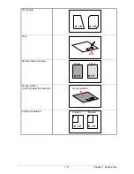
Page 16: ...cations Thickness 0 05 mm to 1 6 mm Width 279 4 mm to 914 4 mm Length 210 mm to 3 600 mm Do not scan the following kinds of originals The original or the scanner may damage Stuck with paste Torn Folded Leading edge Excessively curled a diameter of 50 mm or less Chapter 1 Before Use 1 10 Paste ...

Page 17: ...t square Wet Metal or fabric material Rough surface Carbon paper for example Clipped or stapled K I P K I P K I P K I P Wet Metal Fabric Clipped Stapled Rough surface K I P K I P Chapter 1 Before Use 1 11 ...

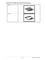
Page 18: ...The following kinds of originals can be read with using a carrier sheet Image quality or the reliability of paper feeding for them is not guaranteed Patched Punched Chapter 1 Before Use 1 12 ...

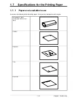
Page 19: ...nting Paper 1 7 1 Papers not available to use Do not use the following kinds of printing paper Doing so may damage the print engine Excessively curled a diameter of 50 mm or less Folded Creased Torn Punched Chapter 1 Before Use 1 13 ...

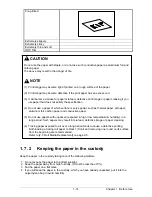
Page 20: ...and conductive paper 5 Do not use papers with unpacked exposed in high low temperature humidity in a long period Such papers may result in mis feed defective image or paper creasing 6 Tracing paper exposed to air over a long period tends to cause a defective printing Both loading a tracing roll paper to Deck 1 front and removing one round on its surface from the beginning are recommended Refer to ...

Page 21: ...a polyethylene bag Void of image occurs when you print with plain paper and tracing paper If you will not make print soon remove the tracing paper from the machine and keep it in a polyethylene bag Low 40 70 High Void of image crease of paper and other problems occurs when you print with plain paper and tracing paper 1 Turn on the Dehumidify Heater if installed 2 Remove the paper from the machine ...

Page 22: ... off CX 8048 2 4 2 3 Roll Media Replacement 2 5 2 4 Toner Cartridge Installation 2 10 2 5 Cut Sheet Media Placement 2 14 2 6 Copying 2 15 2 7 Emergency Stop of Scan or Copy 2 16 2 8 Canceling Sleep Mode 2 17 2 9 Dehumidifying Roll Media 2 18 Chapter 2 Basic Operation 2 1 ...

Page 23: ... 2 WARNING 1 Do not handle the Power Plug with wet hands or you may receive an electrical shock 2 Make sure to earth the machine for safety 3 Do not plug the printer into a multi wiring connector in which other devices are plugged It may overheat the outlet and may result in a fire 4 The outlet must satisfy the following conditions In U S A 120 V plus minus 10 50 60 Hz and 15 A In Europe 220 240 V...

Page 24: ...inute A Ready Indicator on Copy Mode Screen will flash during warming up Ready Indicator Note The screen is shown with available options 4 When the Ready Indicator stops flashing the CX 8048 is ready for operation You can make a copy scan optional or print optional Chapter 2 Basic Operation 2 3 ...

Page 25: ...8 print engine and UI appear to be shut down when you turn off CX 8048 However the controller PC embedded inside the CX 8048 is still operating and will shutdown in approximately two minutes after Power Switch operation Do not unplug the CX 8048 before the controller PC completes its shutdown Doing so may damage data or the device Chapter 2 Basic Operation 2 4 ...

Page 26: ...l media to Roll Deck 1 The same procedure is applied to Roll Deck 2 unless otherwise noted 1 Open Roll Deck 1 and remove an empty roll core 2 2 Raise the lever 3 on Flange 4 and remove 2 Flange 4 from the roll core 2 3 Move a right Slide Guide 5 to match your roll media s width The right and left Side Guides will automatically move together Chapter 2 Basic Operation 2 5 2 2 1 5 5 Roll 1 5 Roll 2 H...

Page 27: ...ully insert Flange into the roll media core so that the inside rim of Flange evenly touches the side face of the roll media Gap Inside Rim Inside Rim Correct Fully inserted Wrong not touching roll side 2 Flange has Stoppers 6 with sharp edge Be sure not to touch them Chapter 2 Basic Operation 2 6 ...

Page 28: ...he roll media by holding both Flanges Lower Flanges onto Slide Guides 5 in Roll Deck NOTE 1 Note the rewinding direction Front to Guide Plate Front to Guide Plate Rear Deck back Rear Deck back 5 3 3 Correct Edge comes from bottom Wrong Edge comes from top continued on the next page Chapter 2 Basic Operation 2 7 ...

Page 29: ...o that the feeding rollers catch the leading edge Chapter 2 Basic Operation 2 8 NOTE Use the rear Feed Knob 11 for Roll Deck 2 NOTE 2 The outside rim 7 of Flange should meet the black triangle 8 marked on Slide Guide Otherwise the roll media may fall in Roll Deck or result in an incorrect media feeding Correct Wrong 9 10 7 8 8 7 11 ...

Page 30: ...n Cutter Knob 13 fully from one side to the other to make a new straight edge Remove the cut portion 13 10 Close Roll Deck Chapter 2 Basic Operation 2 9 NOTE Completely slide Cutter Knob 13 until it stops at either end Not doing so may cause a paper jam Correct Wrong NOTE Be sure to close the Roll Deck fully until it locks at the correct position A paper jam may occur if it is not locked firmly 13...

Page 31: ...2 4 Toner Cartridge Installation 1 Open the Toner Hatch 1 2 Slide the green Lever 2 to the right to unlock the Toner Cartridge Lever 2 is held automatically Chapter 2 Basic Operation 2 10 2 1 ...

Page 32: ...s treatment 4 Pressing down the Cartridge Lock Lever 3 bring up the left side of the Toner Cartridge first and then remove the whole cartridge from the machine Chapter 2 Basic Operation 2 11 NOTE The toner may drop from the toner supply hole and it may scattered into the machine or on the floor if you remove the Toner Cartridge without closing the toner supply hole 5 3 5 4 3 ...

Page 33: ...tridge Lock Lever 3 fit the pin 6 on the left side of cartridge to the groove 7 on the machine side Chapter 2 Basic Operation 2 12 NOTE Please confirm that the Cartridge Lock Lever 3 firmly locks the Toner Cartridge at the correct position It must be at a level position Good No good 6 Press down completely 7 3 ...

Page 34: ...to open the toner supply hole Confirm that the projection 8 if fitted into the notch 9 8 Close the Toner Hatch 1 Chapter 2 Basic Operation 2 13 NOTE It is not necessary to lock the cartridge with the Lever 2 Lever 2 will engage on its own after closing the Toner Hatch 8 9 4 1 2 ...

Page 35: ... insert it into the Bypass Feeder When the leading edge touches the feeding roller the machine automatically carries and sets the paper at the proper position NOTE As a curly cut sheet will cause a mis feed straighten the sheet as far as possible before printing And set the sheet in curl down direction as a mis feed can be avoided Curl up sheets tend to result in a mis feed Correct curl down Incor...

Page 36: ... with face up Then insert it under the Scanner Unit along with Original Guides When the leading edge touches the original feeding roller the machine automatically carries and sets the original at the proper position 3 The CX 8048 will start the print process NOTE The scanner unit does not accept originals automatically during Sleep Mode Touch any area in the touch screen and then insert an origina...

Page 37: ... a copy or scan Pressing the button stops the current reading a document immediately The current printing is stopped as well and is ejected Stop on the touch screen will work as the same function 1 NOTE Do not pull back or hold down the original on Original Table as an attempt to stop feeding it through Scanner Unit Chapter 2 Basic Operation 2 16 ...

Page 38: ...ivity to stop the power supply for Fuser Unit and some other components Sleep Mode is canceled and the machine gets ready when the machine receives a print job through the network the UI is touched and an original is inserted into the scanner See Part 7 4 2 1 Power Save Settings on page 7 9 for further information Chapter 2 Basic Operation 2 17 NOTE 1 It may take time for the machine to get ready ...

Page 39: ...bove kinds of print defect You may be able to fix the above kinds of problem To turn on the Dehumidify Heater press the H side of the Dehumidify Heater Switch on the rear Press its L side to turn off Dehumidify Heater Switch Chapter 2 Basic Operation 2 18 If the media is humidified Normal Print Crease of paper Normal Print If the media is humidified Loss of image NOTE CX 8048 is equipped with the ...

Page 40: ...6 3 1 1 4 Fuser Jam 3 7 3 1 1 5 Accessory Jam 3 8 3 1 1 6 Original Jam 3 9 3 1 2 Others 3 10 3 1 2 1 Initial state 3 10 3 1 2 2 Deck open 3 10 3 1 2 3 Accessory Error 3 10 3 1 2 4 Manual Set NG 3 10 3 1 2 5 Cutter Set NG 3 11 3 1 2 6 Toner Empty 3 11 3 1 2 7 Paper Empty 3 11 3 1 2 8 The door opened during the print 3 11 3 2 Service Call Errors 3 12 Chapter 3 Error Correction 3 1 ...

Page 41: ...th Use cold water to wash in out Using hot water may leave a stain 5 If a paper jam occurs using multiple copy and set copy Jam Recovery screen will appear in the UI Jam Recovery reprints the removed sheets Enter a number of the images to be reprinted with the arrow buttons The available number ranges from 1 to 9 and the default is 2 The number of images to be reprinted is equivalent to the amount...

Page 42: ...er 2 Insert the leading edge of roll paper under the Guide Plate 1 until the edge touches the feeding roller Then rotate the Paper Feeding Knob 2 clockwise so that the feeding rollers catch the roll paper 5 1 2 NOTE The leading edge should be trimmed with a cutter in case of an extreme crease For Roll 2 use the Paper Feeding Knob on the rear side 3 3 Chapter 3 Error Correction 3 3 ...

Page 43: ...o another completely to make a new straight edge 5 2 Leading edge Remove the cut portion NOTE Completely slide Cutter Knob 5 until it stops at either end Not doing so may cause a paper jam Correct Cutter Knob at end Wrong Cutter Knob at middle 5 5 5 Close Roll Deck NOTE Be sure to close the Roll Deck fully until it locks at the correct position A paper jam may occur if it is not locked firmly Chap...

Page 44: ...gine Unit when the Scanner Unit is opened If the Scanner Unit is opened it will hit the bottom of User Interface NOTE 1 Be sure to close the Engine Unit firmly until it is locked at the correct position 2 The mis fed paper can be replaced with a new one or be inserted at the opposite edge to the feeder An extreme crease may cause a paper jam Chapter 3 Error Correction 3 5 ...

Page 45: ...he mis fed paper 3 Close the Engine Unit firmly 1 NOTE Do not open the Engine Unit when the Scanner Unit is opened If the Scanner Unit is opened it will hit the bottom of User Interface NOTE Be sure to close the Engine Unit firmly until it is locked at the correct position Chapter 3 Error Correction 3 6 ...

Page 46: ... opened If the Scanner Unit is opened it will hit the bottom of User Interface 2 Remove the mis fed paper if you find it Go to the later step 4 when the mis fed paper cannot be seen or removed 3 Close the Engine Unit firmly NOTE Be sure to close the Engine Unit firmly until it is locked at the correct position Chapter 3 Error Correction 3 7 ...

Page 47: ... making reference to the User s Manual of concerning device Chapter 3 Error Correction 3 8 WARNING There are extremely hot parts inside the Exit Cover Do not touch any parts in the Heater Unit or you will be burnt Also be careful not to get burnt when you touch the printing paper as it may be very hot NOTE If removed a mis fed paper inside the Exit Cover scattered toner can be adhered to the next ...

Page 48: ... pulling up the Levers 1 and then remove the original 2 Gently press Scanner Unit down and firmly close it 1 NOTE Press down Scanner Unit on both the sides to close it Do not close it by pressing only one side down Chapter 3 Error Correction 3 9 ...

Page 49: ...ssage is indicated when the Roll Deck is opened Close it firmly 3 1 2 3 Accessory Error Any error occurs in the optional device such as Auto Stacker or Folder Clear the error making reference to the User s Manual of concerning device 3 1 2 4 Manual Set NG This message is indicated when a cut sheet paper is inserted to the Bypass Feeder during warming up Remove it from the Bypass Feeder Chapter 3 E...

Page 50: ...en the Toner Cartridge is emptied with the toner Replace the Toner Cartridge with the new one making reference to 2 4 Toner Cartridge Installation on the page 2 10 3 1 2 7 Paper Empty This message is indicated when the roll paper in use is emptied Replace roll paper with the new one making reference to Roll Core 2 3 Roll Media Replacement on the page 2 5 3 1 2 8 The door opened during the print Th...

Page 51: ...otor1 Error E 011 Motor2 Error E 012 Motor3 Error E 020 Counter Error E 031 1st Error E 032 AC Error E 033 Tr Error E 034 Bias Error E 040 Cutter Error E 050 FPGA Error E 070 Dev Error E 080 E 081 Density Sensor Error If any of the above errors appear 1 Turn off CX 8048 and turn it on after an interval of 30 seconds or more 2 If the same error code appears turn off CX 8048 and then unplug the prin...

Page 52: ...Chapter 4 Maintenance page 4 1 Cleaning 4 2 4 1 1 Scanner Unit 4 2 4 1 2 Print Engine 4 4 4 1 3 Touch Screen 4 6 Chapter 4 Maintenance 4 1 ...

Page 53: ...these parts are dirty 1 Turn off CX 8048 2 Open the Scanner Unit pulling up the Levers 1 1 3 Wipe each Scan Glass 2 Feeding Rollers 3 and the inside surface with a soft cloth Use equal volume mixture of water and a neutral detergent 3 2 NOTE Do not use organic solvent glass cleaner and anti static spray for the cleaning Chapter 4 Maintenance 4 2 2 3 ...

Page 54: ... and the inside surface with a soft dry cloth 4 4 4 5 Gently press Scanner Unit down and firmly close it NOTE Press down Scanner Unit on both side to close it Do not close it by pressing only one side down Chapter 4 Maintenance 4 3 ...

Page 55: ...paper dust may accumulates on such part which may result in a defective print image 1 Turn off CX 8048 2 Open the Engine Unit pulling up the Engine Unit Open Levers 1 1 3 Wipe Guide Plate 2 3 black rubber area with a soft dry cloth to remove toner or paper dust 3 2 Chapter 4 Maintenance 4 4 ...

Page 56: ...t touch the drum Adhering a fingermark or sebum on the Drum may cause defective printing b Take off such metal accessories as watch or ring You will have to replace the Drum if you damage the Drum scratching with such accessories c Do not leave the Upper Unit open for more than 10 minutes as the Drum is very sensitive to light Direct sunlight is very harmful 2 Do not use water organic solvent and ...

Page 57: ...4 1 3 Touch Screen Clean the Touch Screen once a week 1 Wipe the Touch Screen with a dry cloth NOTE Do not use water alcohol organic solvent and glass cleaner for the cleaning Chapter 4 Maintenance 4 6 ...

Page 58: ......

Page 59: ...UTAX GmbH Ohechaussee 235 22848 Norderstedt Germany ...

Reviews: