Triton CINCDES08W Installation And Operating Instructions Manual Download Page 36

In the event of a product fault or complaint occurring, 
the following procedure should be followed:
DO NOT REMOVE THE PRODUCT

1.  Telephone Customer Experience on 

024 7637 2222

 having 

available your details including post code, the model number 
and power rating of the product, together with the date of 
purchase and, where applicable, details of the particular fault.

2.  If required, the Customer Experience Advisor will arrange for a 

qualifi ed engineer to call.

3.  All products attended to by a Triton service engineer must be 

installed in full accordance with the Triton installation guide 
applicable to the product. Every product pack contains an 
installation guide, however, they can also be downloaded free at 
www.tritonshowers.co.uk. 

4.  Our engineer will require local parking and if a permit is required, 

this must be available to the engineer on arrival at the call.

5.  If loft access is required for isolation or to complete a repair, 

the loft must have a fi xed access ladder and be boarded, with 
appropriate lighting from the access point to and around the 
repair area.

6.  It is essential that you or an appointed representative, who must 

be over 18 years of age, is present for the duration of the service 
engineer’s visit. If the product is in guarantee you must produce 
proof of purchase.

7.  Where a call under the terms of guarantee has been booked 

and the failure is not product related (i.e. scaling and furring, 
incorrect water pressure, pressure relief device operation or 
electrical/plumbing installation fault) a charge will be made. A 
charge will also be issued if nobody is at the property when the 
service engineer calls or adequate parking/permit is not available.

8.  If the product is no longer covered by the guarantee an up-front 

fi xed fee will be charged before the site visit.

9.  Your receipt must be retained as proof of purchase. Should proof 

of purchase not be available on an ‘in-guarantee’ call, or should 
the service engineer fi nd that the product is no longer under 
guarantee, the engineer will charge the same fi xed price and 
will request payment prior to departing. If payment is not made 
on the day an administration charge will be added to the fi xed 
charge.

10.  If a debt is outstanding from a previous visit, or from any other 

Triton purchase, Triton reserves the right to withhold service until 
the debt has been settled.

11.  Triton takes the health, safety and wellbeing of its employees 

very seriously and expects customers to treat all staff members 
with respect. Should any employee feel threatened or receive 
abuse, either verbally or physically, Triton reserves the right to 
withhold service.

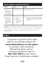
Replacement Parts Policy

In line with AMDEA guidelines, Triton retains functional spares 
for as long as there is a market for them and in most cases, well 
beyond.  Due to the vast array of product types, the life cycle of 
products can vary and therefore so can the length of time parts 
can be supplied. Spare parts can be ordered via our online spare
parts store or by telephoning Triton Customer Experience team
on 

024 7637 2222

. Payment should be made by

credit / debit card (excluding American Express or Diners Card).
Payment can also be made by pre-payment of a pro-forma
invoice, by cheque or postal order.

Telephone orders are based on information given during 
the call.  Before contacting Triton, please verify your 
requirements using the Triton website or your professional 
installer. Triton cannot accept liability for incorrect part 
identifi cation. 

TRITON UK STANDARD GUARANTEE

This guarantee applies only to products installed within the 
United Kingdom and does not apply to products used
commercially.  This guarantee does not affect your statutory 
rights.

With the exception of accessories, Triton guarantee the 
product against all manufacturing defects for a period of 

2 years

 (for domestic use only) from the date of purchase, 

provided that it has been installed by a competent person in 
full accordance with the fi tting instructions. 

All accessories such as shower heads, hoses and riser rails carry 

1 year

 parts only guarantee against manufacturing defects.

Any part found to be defective during this guarantee period 
we undertake to repair or replace at our option without 
charge, so long as it has been properly maintained and
operated in accordance with the operating instructions and 
has not been subject to misuse or damage. This product must 
not be taken apart, modifi ed or repaired except by a person 
authorised by Triton. 

What is not covered:

1.  Breakdown due to:  

a) 

use other than domestic use by the property 

occupants; 

b)

 wilful act or neglect; 

c) 

any malfunction resulting from the incorrect use or 

quality of electricity, gas or water or incorrect setting of 
controls; 

d) 

failure to install in accordance with this installation 

guide.

2.  Claims for missing parts once the product has been 

installed.

3.  Repair costs for damage caused by foreign objects or 

substances.

4.  Total loss of the product due to non-availability of parts.

5.  Compensation for loss of use of the product or 

consequential loss of any kind.

6.  Call out charges due to an abortive visit or where no fault 

has been found with the appliance.

7.  The cost of repair or replacement of isolating switches, 

electrical cable, fuses and/or circuit breakers or any other 
accessories installed at the same time. Replacement of the 
Pressure Relief Device that only activates when the shower 
outlet is blocked is also excluded. 

8.  The cost of routine maintenance, adjustments, overhaul 

modifi cations or loss or damage arising therefrom, 
including the cost of repairing damage, breakdown, 
malfunction caused by corrosion, furring, frost or exposure 
to freezing conditions.

9.  Callout charges where the water supply cannot be 

isolated, this includes consequential losses arising from 
unserviceable supply valves, or inaccessible product or 
valves located in a loft space without suitable access.

For the latest Terms & Conditions please see:

www.tritonshowers.co.uk/terms

PLEASE NOTE PRODUCT REGISTRATION IS ONLY

AVAILABLE TO UNITS PURCHASED & INSTALLED IN THE UK

Triton Showers
Triton Road
Nuneaton
Warwickshire, CV11 4NR

Triton is a division of Norcros Group (Holdings) Limited

Customer Experience: 024 7637 2222

Trade Installer Hotline: 024 7637 8344

www.tritonshowers.co.uk

E-mail: [email protected]

E-mail: [email protected]

UK SERVICE POLICY

Triton reserve the right to change product specifi cation without prior notice. E&OE. © TRITON SHOWERS 2020

Summary of Contents for CINCDES08W

Page 1: ...ions before commencing installation and keep it for future reference The shower installation MUST be carried out by a suitably qualified person in the sequence of this instruction book IMPORTANT SAFETY ADVICE Failure to use genuine Triton parts may cause injury and invalidate your guarantee The shower unit MUST BE switched off at the isolating switch when not in use This is a safety procedure reco...

Page 2: ... to be permanently connected to the water mains and not connected by a hose set The water inlet of this appliance must only be connected to mains cold water only The water inlet must never be connected through any other water heating system WARNING This appliance is not to be used for a potable water supply A suitable double pole isolation switch for supply disconnections must be incorporated in t...

Page 3: ... supply pipe must be flushed to clear debris before connecting to the shower unit 2 3 Do NOT solder fittings near the shower unit as heat can travel along pipework and damage components 2 4 DO NOT fit any form of outlet flow control as the outlet acts as a vent for the heater can 2 5 DO NOT use excessive force when making connections to the flexible hose or showerhead finger tight is sufficient 2 6 All p...

Page 4: ... care mark requirements the unit must not be able to run hotter than 41 C this is used in healthcare or special needs environments The Omnicare thermostatic unit is factory set at 47 C see Adjusting the Maximum Temperature section on how to adjust the MAXIMUM temperature to 41 C At a selected showering temperature the unit will provide the optimum flow rate possible Note the flow rate for any show...

Page 5: ...ic Producers take back scheme PTS registration number WEE EJ3466QV All our electric products are labelled accordingly with the crossed out wheeled bin symbol This indicates for disposal purposes at end of life that these products must be taken to a recognised collection points such as local authority sites local recycling centres this will be free of any charges Do not return to Triton Showers OMN...

Page 6: ...rements Plumbing Siting of the shower Electrical Installation Plumbing Fixing to the Wall Electrical Drain Pump Connectivity Shower Settings Setup Commissioning Adjusting the Maximum Temperature Stop BEAB Care Fitting the Cover Operating Instructions Maintenance Cleaning the Filter BEAB Care Fault finding Troubleshooting Spares UK Service policy Guarantee etc 2 4 4 5 5 7 8 9 9 9 10 11 12 14 15 16 ...

Page 7: ...itres per minute 50kPa 0 5 Bar at 8 litres per minute under adnormal conditions Maximum Static Pressure 1000 kPa 10 bar Maximum inlet temperature 28 C 20 C BEAB Care Minimum inlet temperature 2 C 5 C BEAB Care Inlet connection BSP male thread for 15mm compression fitting Outlet connection BSP male thread MATERIALS ABS Backplate cover controls showerhead Minerally insulated corrosion resistant meta...

Page 8: ...d valve 6 7 5 8 9 10 11 12 13 14 15 16 5 2 Inside the unit 4 4 1 Top cable and pipe entry 2 Top left cable entry 3 Bottom cable and pipe entry 4 Rear cable and pipe entry 5 Wall screw fixings 6 Cover screw fixings 7 Thermal safety cut out 8 Power PCB 14 Water inlet 15 Pressure relief device PRD 16 Shower outlet 17 Splashguard not shown 18 Start Stop PCB 19 Control PCB 19 18 Inside the Cover 3 1 5 ...

Page 9: ...9 SPECIFICATION DIMENSIONS ENTRY POINTS 245mm 361mm 112mm 245mm 361mm 126mm Omnicare Omnicare Design Diagram Key Water Entry Points Electrical Cable Entry Points ...

Page 10: ...e isolating valve should be located close to the shower unit 7 Important Before completing the connection of the water supply to the inlet of the shower flush out the pipework to remove all swarf and system debris This can be achieved by connecting a hose to the pipework and turning on the mains water supply long enough to clear the debris to waste 8 Important The unit must be mounted on a flat su...

Page 11: ...ed either side of riser rail Height of shower should be a minimum of 750mm from base Spillover level Height of showerhead and shower to suit user s requirement WARNING The shower MUST NOT be positioned where it will be subjected to freezing conditions Fig 1 Diagrammatic view not to scale For illustration purposes only Kits may vary ...

Page 12: ... fuse way which will take the fuse or Miniature Circuit Breaker MCB necessary for the shower rating 7 If your consumer unit has a rating below 80A or if there is no spare fuse way then the installation will not be straightforward and may require a new consumer unit serving the house or just the shower Contact a professional electrician local electricity company for advisement 8 For close circuit p...

Page 13: ...ther circuits by at least twice the diameter of the cable or conduit The current rating will be reduced if the cabling is bunched with others sur rounded by thermal loft or wall insulation or placed in areas where the ambient temperature is above 30 C Under these conditions derating factors apply and it is necessary to select a larger cable size In the majority of installations Fig 2 the cable wil...

Page 14: ...tep Step Remove the front cover assembly 2 screws securing the splashguard and the splashguard 2 Step Step Rotate inlet fitting to suit the required water supply pipe entry position Rear Entry Top Entry Bottom Entry 3 Step Step Complete all the plumbing pipework Ensure that any soldering of pipework is done away from the shower as heat can travel along pipework and damage components IMPORTANT Befo...

Page 15: ... 1 2 3 Temporarily connect the shower unit to plumbing pipework Using the backplate as a template making sure it is level mark the fixing holes Use all 3 screw holes to secure the unit Remove the unit from the wall Drill the fixing holes Use appropriate wall plugs Reconnect the shower unit to plumbing pipework and secure the unit to the wall using appropriate screws IMPORTANT Ensure the unit is se...

Page 16: ...k to a minimum Fully tighten the terminal block screws and make sure that no cable insulation is trapped under the screws IMPORTANT Loose connections can result in cable overheating DO NOT switch on the electricity supply Earth cable Green Yellow to Neutral cable Blue or Black to N Live cable Brown or Red to L 7 Step Step Refit the splashguard and secure with the 2 fixing screws 8 1 Step Step Term...

Page 17: ...er is turned off a signal is sent again to the drain pump electronics telling the pump to stop generally after a preset time delay This type of pump makes no allowance for the flow rate of the water from the shower the gulp or speed of the pump is fixed ON 1 2 3 4 5 DIP switch 4 On Analogue Pump Setting The pump manufacture provides a two core cable for connection to the shower unit Connect the dr...

Page 18: ... by a flow sensor fitted within the shower unit and communicates this information to the drain pump through the digital signal The pump manufacture provides a three core cable for connection to the shower unit Connect the drain pump control wire as below 1 5V to 24V 2 0V dc 3 Signal Note Please refer to the relevant pump manufacturers installation instructions for pump connection relevant IEE regu...

Page 19: ...On Audible Feedback On Factory Setting DIP switch 1 Off Audible Feedback Off Timed Shutdown DIP switch 2 Off DIP switch 3 Off Timed shutdown of 5mins DIP switch 2 Off DIP switch 3 On Timed shutdown of 10mins DIP switch 2 On DIP switch 3 Off Timed shutdown of 20mins Factory Setting DIP switch 2 On DIP switch 3 On Timed shutdown of 30mins This function provides an audible notification to specific sh...

Page 20: ...Step 13 Step Step Turn on the water supply to the shower unit at the isolating stop valve Switch on the electricity supply to the unit at the isolating switch Water will start to flow from the shower hose Allow water to flow for approximately 60 seconds this will allow the air to bleed from the installation Isolate the electricity to the unit at the isolating switch The water will cease to flow Re...

Page 21: ... t t i n g at either 4 1 or 43 C w h e n s e t t i n g a t S e l e c t p o s i t i o n A 4 7 C I n s t a l l a t i o n P l e a s e r e f e r t o I n s t r u c t i o n s Knob Adaptor Rotate the knob adaptor clockwise until it hits the stops on the valve mechanism as shown above Rotate the splined spindle until the inner arrow aligns with the 43 C mark for maximum temperature to be 43 C Rotate the s...

Page 22: ...i o n B when E n s u r e S e l ector is set s e t t i n g at either 4 1 or 43 C w h e n s e t t i n g a t S e l e c t p o s i t i o n A 4 7 C I n s t a l l a t i o n P l e a s e r e f e r t o I n s t r u c t i o n s Replace the knob adaptor so it s in the orientation above Refit the screw securing the knob adaptor 14 5 14 4 14 6 INSTALLATION ...

Page 23: ...ble connector can be fitted to the socket only one way 14 1 14 2 14 3a 14 4 14 5 Temporarily fit the cover to the shower unit minor adjustment of the temperature dial may be necessary to align with the valve Secure the cover in position with one of the retaining screws Restore the electricity supply to the shower Check the water temperature is within the range of 5 20 C Check the terminal voltage ...

Page 24: ...m entry has been chosen fit the appropriate cut out in the top of the cover If top entry has been chosen fit the appropriate cut out in the bottom of the cover Guide the cover into position so that the temperature selector locates correctly onto the valve minor adjustment of the temperature dial may be necessary to align with the valve Apply slight pressure to the cover and secure in position with...

Page 25: ...d 3 Adjust the Temperature Control to your preference Rotating the control clockwise will make the water hotter rotating the control anti clockwise will make the water cooler 4 Check the temperature of the water before showering HOT COLD 5 Stop the shower by pressing the Start Stop button Water will continue to flow for a few seconds purging any remaining hot water from the shower Switch OFF the e...

Page 26: ...ted indicator will go off Pressing the start stop button will then restart the unit Start Stop button Power on indicator Shutdown indicator Temperature control Low flow indicator OPERATING INSTRUCTIONS Shutdown Indicator This will illuminate with a yellow light if either a Timed Shutdown has been initiated by the shower unit or the Start Stop button has been pressed to stop the shower When a Timed...

Page 27: ...nts will be reduced to maintain the shower temperature When the flow of water through the unit returns to normal power to the elements will be automatically restored to the setting at the time of interruption Safety Cut out The unit is fitted with an over temperature safety device In the event of abnormal operation which could cause unsafe temperatures within the unit the device will disconnect th...

Page 28: ... competent person Switch off the electricity and water supply at the mains The inlet filter is situated inside the water inlet fitting To gain access to the filter remove the cover Unscrew the inlet filter cap on the water inlet fitting Inspect the o ring for damage when the filter is removed Do not over tighten the filter cap on reassembly When cleaning the filter DO NOT use a sharp object as it ...

Page 29: ...ry out the following sequence a record the supply voltage at the terminals of the appliance b record the outlet water temperature and the flow rate resulting from the setting c reduce the water supply flow rate at the inlet of the appliance by at least 50 or to the lowest value at which the appliance continues to deliver an output of heated water whichever is the greater pressure d record the outl...

Page 30: ...minals of the appliance b Record the outlet water temperature and the flow rate resulting from the setting c Reduce the water supply flow rate at the inlet of the appliance by at least 50 or to the lowest value at which the appliance continues to deliver an output of heated water whichever is the greater pressure d Record the outlet water temperature and the reduced flow rate NOTE The outlet water...

Page 31: ...ature then the next in service test can be deferred to 24 to 28 weeks after commissioning c If small changes e g 1 to 2 C in outlet water temperatures are recorded in both of these periods necessitating adjustment of the outlet water temperature then the next in service test should be carried out at 18 to 21 weeks after commissioning d If significant changes e g 2 C in outlet water temperatures ar...

Page 32: ...ls again consult a qualified electrician 1 2 1 Power cut Check other appliances and if necessary contact local Electricity Supply Co 1 2 2 Have unit checked Contact Customer Experience 1 3 1 The thermal cut out safety device has operated Have the unit checked by a suitably qualified service engineer or contact Customer Experience 1 4 1 The PCB has an NTC safety device which has operated Have the u...

Page 33: ...utlet thermistor failed 5 Pressure relief device has operated water ejected from PRD tube 5 1 Blocked showerhead 5 2 Twisted blocked flexible shower hose 5 3 Showerhead not removed while commissioning 5 1 1 Clean sprayplate and then fit a new PRD 5 2 1 Check for free passage through hose Replace hose if necessary and then fit new PRD 5 3 1 Fit new PRD Commission unit with showerhead removed Proble...

Page 34: ...omer Experience Problem Cause Action Note Identify cause of operation before fitting new PRD unit When fitting a new PRD follow the commissioning procedure It is advised all electrical maintenance repairs to the shower should be carried out by a suitably qualified person In the unlikely event of unit failure other than detailed in the fault finding page please contact Customer Experience for advic...

Page 35: ...owing alternative formats Braille Extra Large Print Audio CD Alternative format User Instructions are available for the this shower and the Remote start stop button accessory Should you require a copy of the alternative User Instructions please contact Triton Customer Experience on 024 7637 2222 ...

Page 36: ...iners Card Payment can also be made by pre payment of a pro forma invoice by cheque or postal order Telephone orders are based on information given during the call Before contacting Triton please verify your requirements using the Triton website or your professional installer Triton cannot accept liability for incorrect part identification TRITON UK STANDARD GUARANTEE This guarantee applies only t...

Reviews: