background image

11

Cable Length Test

Performing a Cable Length Test

1.

  Connect a cable to the appropriate port on the Main Tester unit, using 

the RJ45 port marked 

Main

 for Cat5 / Cat6 cables. You can choose to 

connect the other end to the Remote Tester unit or not.

2. 

Navigate to the 

Type

 option in the LCD Interface Menu and select the 

type of cable you have connected by pressing the 

Enter

 button to toggle 

through the options.

3. 

Once you’ve selected the appropriate cable, navigate to the 

Unit

 option 

and select the unit of measurement you want to display results in by 
pressing the 

Enter

 button to toggle through the options.

4.

  Once you’ve selected the unit of measurement, navigate to the 

Cable 

Length

 option and press the 

Enter

 button to initiate the test.

5.

  A screen will appear indicating the tester is identifying the length of the 

connected cable, followed by the results of the test. The possible test 
results are listed below.

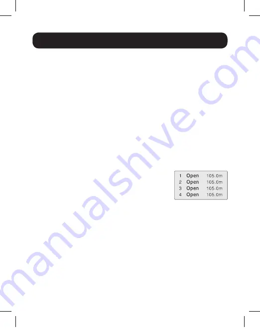
a. Normal Pairing and Length

 – When there  

are no faults in the cable pairing, results like  
those to the right will be shown. If you have  
the other end of the cable connected to the  
Remote Tester unit, the middle column of  
text will show M-R. If you do not have the remote end of the cable 
connected, the middle column of text will show OPEN. The Pins will 
be displayed in the left column of text, and the calculated length in 
the right column. Press the 

Up

 and 

Down 

buttons to toggle to pins 

that are not displayed on the screen.

b. Abnormal Pairing and Length

 – When there are faults found in the 

cable pairing, test results similar to the 

Normal Pairing and Length


results will be shown, except for any pins with faults, the length 
shown in the right column will be shorter than that of the rest of the 
cables. This will indicate the location of the fault along the wire.

19-04-414-9334DF-EN.indd   11

6/21/2019   8:26:41 AM

Summary of Contents for T010-001-K

Page 1: ...Street Chicago IL 60609 USA www tripplite com support Copyright 2019 Tripp Lite All rights reserved WARRANTY REGISTRATION Register your product today and be automatically entered to win an ISOBAR surg...

Page 2: ...lt and location of cables Easy to use LCD interface Test cable wiring for open short cross reverse and pairing connection Determine location of open circuit position Determine the length of a cable wh...

Page 3: ...and fault test 6 UP Button Press to move up through the menu in the LCD interface 7 DOWN Button Press to move down through the menu in the LCD interface 8 ON OFF Button Press to turn the Main Tester...

Page 4: ...tracing 3 Volume Slider Move it up and down to adjust the volume of the tone generated during cable tracing 4 Test Button Press to send the tone through the cable when performing cable tracing 5 Flas...

Page 5: ...5 Remote Tester Unit 1 RJ45 Port 2 USB A Port 3 RJ11 Port 4 BNC Port 4 1 3 2 19 04 414 9334DF EN indd 5 6 21 2019 8 26 41 AM...

Page 6: ...ting Cable Length Used to perform a Cable Length test Scan Cable Used when performing the Wire Tracking function Unit Determine the unit of measurement in which to display length information Calibrati...

Page 7: ...avigate to the Type option Press the Enter button to toggle between the cable type options until you get to the type of cable you are testing 4 After selecting the cable type navigate to the Wire Mapp...

Page 8: ...ting the open pins with an X d Open Circuit on Far End If there are open pins found on the far end of the cable results like those to the right will appear indicating the open pins with an X e Open Ci...

Page 9: ...se to the right i Open Circuit Installed Cable When testing installed cable that connects from the Main Tester unit to a wallplate switch or other device open circuits are indicated by results like th...

Page 10: ...and press the Enter button to initiate calibration 5 A screen will appear asking if you want to proceed Choose Yes and press the Enter button to proceed with calibration 6 The tester will measure the...

Page 11: ...of the connected cable followed by the results of the test The possible test results are listed below a Normal Pairing and Length When there are no faults in the cable pairing results like those to t...

Page 12: ...Menu and select the type of cable you have connected by pressing the Enter button to toggle through the options 3 Once you have selected the cable type navigate to the Scan Cable option and press the...

Page 13: ...OFF button and continue holding down the UP and DOWN buttons until a menu appears on the screen 3 Scroll down until con1 8 thro appears on the screen then press the ENTER button A similar screen will...

Page 14: ...appear again 8 Press the DOWN button twice to exit recalibration settings 9 Scroll down and press the ENTER button once Save Off appears on the screen When completed Sys Adj End will appear on the scr...

Page 15: ...DVISED OF THE POSSIBILITY OF SUCH DAMAGE Specifically TRIPP LITE is not liable for any costs such as lost profits or revenue loss of equipment loss of use of equipment loss of software loss of data co...

Page 16: ...16 1111 W 35th Street Chicago IL 60609 USA www tripplite com support 19 04 414 93 34DF_RevB 19 04 414 9334DF EN indd 16 6 21 2019 8 26 42 AM...

Reviews: