background image

37

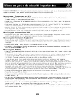
Installation 

(suite)

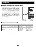
CONNEXION DU MODULE EXTERNE DE BATTERIE (requise)

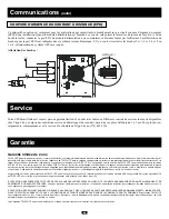
Connecter le module de batterie au module d'alimentation. Consulter le
manuel du propriétaire qui vient avec votre module de batterie. Insérer com-
plètement le connecteur à l'extrémité du câble du module de batterie dans le
connecteur du panneau arrière du module d'alimentation. Il peut y avoir de
petites étincelles; c'est normal. REMARQUE : Le module d'alimentation ne
contient pas de batteries internes et ne démarrera pas avant qu'un module de
batterie soit connecté. Les modules de batterie sont complètement chargés
avant leur expédition. Cependant, afin d'obtenir une pleine capacité de sec-
ours (en particulier si le module de batterie a été entreposé pour une longue
durée) après que le système a été connecté à une source d'alimentation du
secteur, laisser le module se recharger pendant 12 heures. Une fois l'ond-
uleur UPS en marche, il rechargera les batteries et maintiendra le niveau de
charge automatiquement. Si nécessaire, connecter des modules de batterie
supplémentaires en chaîne avec chaque câble de module inséré dans le con-
necteur du module précédent.

REFER TO USER'S MANUAL FOR TORQUING 

SPECIFICATIONS, USE COPPER CONDUCTORS ONLY. 

UTILISER SEULEMENT LES CONDUCTEURS DE CUIVRE. 

Module de batterie 

Panneau arrière

Module d'alimentation 

Panneau arrière

VÉRIFICATION DE L'ÉTAT DE LA BATTERIE

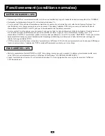
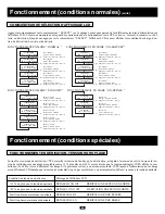
Quand l'UPS fonctionne sur la batterie, l'alarme et l'affichage LCD vous alertent tous les deux sur l'état de charge de la batterie de l'UPS.

État de charge de la batterie

Alarme

Afficheur LCD

PLEINE

Bip court (toutes les deux secondes) ON BATTERY

(BATTERIE EN FONCTION

BATT = XXV XX%

BATT = XXV XX %)

FAIBLE

Bip court (toute les 1/2 seconde)

BATTERY LOW

(BATTERIE FAIBLE

BATT=XXV XX%

BATT = XXV XX %)

DÉCHARGÉE

Bip continu

BATTERY UNDER

(BATTERIE DÉCHARGÉ

SHUT DOWN

MISE HORS SERVICE)

Summary of Contents for SmartOnline 3-Phase 10kVA

Page 1: ...220 230 240V AC 1 2W For all UPS system modules power module and battery module sold either separately or combined Select UPS system modules may include separate instruction or warning sheets which s...

Page 2: ...n your battery module are recyclable Refer to local codes for disposal requirements or if in the USA call 1 800 SAV LEAD 1 800 728 5323 for complete recycling information CAUTION Do not dispose of the...

Page 3: ...lation and start up and after the ON OFF Switch is turned ON 4 I P Input LED This green light will illuminate constantly to indicate an AC input supply is present 5 AC DC Converter LED This green ligh...

Page 4: ...t a connection to a charged battery module Refer to the battery module owner s manual for connection instructions and safety warnings 5 Exhaust Fan This cools and ventilates the inside of the UPS 6 AS...

Page 5: ...olling or tipping 17 Battery Module Input Connector Use this connector to daisy chain additional battery modules to the first Remove the cover panel for access Refer to the battery module s owner s ma...

Page 6: ...ture rating of 70 C and 6 AWG size to connect your UPS to an AC power supply and your equipment to your UPS WIRING CONNECTIONS Connect your wiring to the input and output terminal blocks located on th...

Page 7: ...connected to a utility power source allow the battery module to recharge for 12 hours Once the UPS system is in use it will charge the bat teries and maintain the charge level automatically If needed...

Page 8: ...his operation to succeed Press and hold both the Battery Start switch and the ON OFF switch for three seconds to start your UPS in ON BATTERY mode Note that some electronic equipment may draw more amp...

Page 9: ...starting from battery the BATTERY LED will be lit and the I P and BYPASS LEDs will not The final LCD display in the diagram below appears when the UPS is operating normally under utility supplied AC...

Page 10: ...ough different power readings on the LCD Display The LCD Display will show which one of four operational modes your UPS is currently in Normal Economy On Battery or Bypass Also as you press the SELECT...

Page 11: ...long as the batteries remain charged these warnings should be acted on immediately Battery Charge Warning LCD Display Message Battery charge nearly depleted BATTERY LOW Low battery shutdown LOW BATTE...

Page 12: ...female DB9 port connects your UPS via an RS 232 cable to a workstation or server equipped with Tripp Lite software The port uses RS 232 communications to report UPS status and power conditions Using...

Page 13: ...C power supply Pin 7 Low battery alarm Pin 8 Operation on inverter Pin 9 Operation on battery AS 400 INTERFACE TABLE Pin 6 5 Pin 7 5 Pin 8 5 Pin 9 5 Battery OFF ON ON Low Battery OFF ON ON ON Direct M...

Page 14: ...n authorized TRIPP LITE service center with transportation charges pre paid and must be accompanied by a brief description of the problem encountered and proof of date and place of purchase This warra...

Page 15: ...ies 102 continuous 102 125 1 min 125 150 30 sec 150 2 sec Short Circuit Capability 160A Crest Factor 3 1 Battery Battery Type 12V 9 AH Battery Quantity 20 Protection 2x 30A 600V fuse Typical Backup Ti...

Page 16: ...ccionable por el usuario 220 230 240V C A 1 2W Para todos los sistemas de m dulos UPS m dulos de corriente el ctrica y m dulos de bater a vendidos por separado o de forma combinada Ciertos modelos sel...

Page 17: ...s que contiene el m dulo de bater as son reciclables Refi rase a las regulaciones locales para su desecho o si se encuentra en los Estados Unidos llame al 1 800 SAV LEAD 1 800 728 5323 para recibir in...

Page 18: ...ido el interruptor 4 I P Input LED Detector de Entrada Esta luz verde se iluminar de manera constante para indicar que existe un suministro con stante de corriente alterna 5 AC DC Converter LED Conver...

Page 19: ...se al manual de usuario para m dulos de bater as para las instrucciones de conexi n y advertencias de seguridad 5 Exhaust Fan ventilador Enfr a y ventila el interior del UPS 6 AS 400 Interface Port Pu...

Page 20: ...e voltee 17 Battery Module Input Connector Conector de Entrada del Modulo de Bater a Utilice este conector para conectar en serie m du los adicionales de baterias al primero Retire el panel de cubiert...

Page 21: ...XIONES DE CABLEADO Conecte sus cables a los bloques de terminales ubicados en los paneles posteriores de su UPS v ase el diagrama debajo PRECAUCION El personal cualificado deber seguir todos los proce...

Page 22: ...la toma el ctrica prin cipal permita que el m dulo de bater as se recargue durante 12 horas Una vez que el sistema UPS est en uso cargar las bater as y mantendr la carga de forma autom tica Si lo nece...

Page 23: ...e esta operaci n tenga xito Presione y aguante el interruptor de encendido de bater a Battery Start y el interruptor ON OFF por tres segundos para encender su UPS en la modalidad de BATER A ON BATTERY...

Page 24: ...exhibici n final en el visualizador LCD que aparece en el diagrama mostrado abajo aparece cuando la UPS est funcionando normal mente bajo corriente de entrada de toma general C A O O O AC INPUT OK BA...

Page 25: ...encendida salida XXXV XX XHz Apriete select Bater a encendida batt XXXV XX Apriete select Operaci n Condiciones Normales continuaci n INTERRUPTOR PARA LA SELECCI N DEL VISUALIZADOR LCD DISPLAY Presio...

Page 26: ...ser corregidas inmediatamente Advertencia de Carga de Bater a Mensaje en el LCD Carga de bater a baja BATTERY LOW BATERIA BAJA Bater a baja se aproxima el cierre LOW BATTERY SHUT DOWN BATERIA BAJA SE...

Page 27: ...puerto de hembra DB9 conecta su UPS v a un cable RS 232 a una terminal de trabajo o un servidor equipado con software de Tripp Lite El puerto utiliza las comunicaciones RS 232 para divulgar las condic...

Page 28: ...CTO A LA RED INVERSOR TABLA INTERFASE AS 400 Polo 6 5 Polo 7 5 Polo 8 5 Polo 9 5 Bater a Apagado Encendido Encendido Bater a Baja Apagado Encendido Encendido Encendido Suministro Directo Encendido Apa...

Page 29: ...centro de servicio autorizado de TRIPP LITE con las cargas de transporte pagadas por adelantado y se deben acompa ar por una breve descripci n del problema encon trado y la prueba de la fecha y el lug...

Page 30: ...rga 102 continuous 102 125 1 min 125 150 30 sec 150 2 sec Capacidad de Cortocircuito 160A Factor Cresta 3 1 Bater a Tipo de Bater a 12V 9 AH Cantidad de Bater a 20 Protecci n 2x 30A 600V fuse T pico t...

Page 31: ...ectionnable par l usager 220 230 240V CA 1 2W Pour tous les modules d onduleurs UPS module d alimentation et module de batterie vendus soit s par ment ou combin s Les modules d onduleur UPS s lectionn...

Page 32: ...Les batteries de votre module de batterie sont recyclables Consulter les codes locaux pour les exigences d limination des d chets ou aux U appeler le 1 800 SAV LEAD 1 800 728 5323 pour des renseignem...

Page 33: ...installation et le d marrage et apr s que le commutateur ON OF ait t plac sur ON 4 DEL I P entr e La lumi re verte sera constamment allum e pour indiquer la pr sence de l alimentation d entr e CA 5 Vo...

Page 34: ...le de batterie pour les directives de connexion et les mises en garde de s curit 5 Ventilateur d chappement Il refroidit et ventile l int rieur de l UPS 6 Port d interface AS 400 Ce port femelle DB9 c...

Page 35: ...17 Connecteur d entr e du module de batterie Utiliser ce connecteur pour connecter en cha ne les modules de batterie suppl mentaires au premier Enlever le couvercle du panneau pour l acc s Voir le ma...

Page 36: ...et son calibre de 6 AWG pour connecter votre UPS une alimentation CA et votre quipement votre UPS CONNEXIONS DE C BLAGE Connecter votre c blage aux blocs de jonction d entr e et de sortie situ s au ba...

Page 37: ...laisser le module se recharger pendant 12 heures Une fois l ond uleur UPS en marche il rechargera les batteries et maintiendra le niveau de charge automatiquement Si n cessaire connecter des modules d...

Page 38: ...nt pour que cette op ration r ussisse Appuyer sur le commutateur Battery start et le commutateur ON OFF et les maintenir pendant trois secondes pour d marrer votre UPS en mode BATTERIE Noter que certa...

Page 39: ...et BYPASS L affichage LCD final dans le sch ma ci dessous appara t quand l UPS fonctionne normalement sous alimentation CA de secteur Ou Ou Ou AC INPUT OK BATTERY OK AC DC OK WAIT TESTING INVERTER ON...

Page 40: ...atterie En R XXX V X XX Hz Appuyer sur la touche select Sur batterie En S XXX V T XXXV Appuyer sur la touche select Sur batterie Sortie XXX V X XX Hz Appuyer sur la touche select Sur batterie Batterie...

Page 41: ...Mise en garde de charge de batterie Message de l afficheur LCD Charge de batterie presque puis e BATTERY LOW BATTERIE FAIBLE Mise hors service de batterie faible LOW BATTERY SHUT DOWN BATTERY FAIBLE F...

Page 42: ...u un serveur quip du logiciel Tripp Lite Ce port utilise les communications RS 232 pour rapporter le statut et les conditions d alimentation de l UPS Gr ce ce port le logiciel Tripp Lite peur surveill...

Page 43: ...de batterie faible Broche 8 Fonctionnement sur onduleur Broche 9 Fonctionnement sur batterie TABLEAU DE L INTERFACE AS 400 Broche 6 5 Broche 7 5 Broche 8 5 Broche 9 5 Batterie Arr t Marche Marche Bat...

Page 44: ...LITE Les produits doivent tre retourn s TRIPP LITE ou un centre de service autoris de TRIPP LITE avec les frais de port pr pay s et doivent tre accompagn s d une br ve description du probl me et de la...

Page 45: ...continue 102 125 1 mn 125 150 30 s 150 2 s Capacit de court circuit 160 A Facteur de cr te 3 1 Batterie Type de batterie 12V 9 Ah Nombre de batteries 20 Protection Fusible de 2 x 30 A 600 V Dur e nor...

Page 46: ...ngsspannung Spannung Phase vom Benutzer ausw hlbar 220 230 240V AC 1 2W F r alle UPS Systemmodule Stromversorgungsmodul und Batteriemodul die entweder getrennt oder kombiniert verkauft werden Ausgew h...

Page 47: ...r Entsorgungsanforderungen oder rufen Sie falls Sie in Amerika leben 1 800 SAV LEAD 1 800 728 5323 um vollst ndige Recyclinginformationen zu erhalten ACHTUNG Entsorgen Sie die Batterien nicht in Feuer...

Page 48: ...und nachdem der ON OFF Schalter auf ON Ein geschaltet ist 4 I P Stromeingang LED Dieses gr ne Licht leuchtet konstant auf um anzuzeigen dass die Wechselstromzufuhr vorhanden ist 5 AC DC Konverter LED...

Page 49: ...ndbuch des Batteriemoduls nach Anweisungen zum Anschluss und nach Sicherheitswarnungen 5 Exhaust Fan K hler Dieser k hlt das Innere des UPS 6 AS 400 Interface Port AS 400 Schnittstellenanschluss Diese...

Page 50: ...eitungen 16 Stabilizers Stabilisatoren Diese verhindern dass Ihr UPS rollt oder umkippt 17 Battery Module Input Connector Batteriemoduleingangsverbindung Verwenden Sie diesen Anschluss um zus tzliche...

Page 51: ...CHL SSE Verbinden Sie Ihre Verkabelung mit den Eingangs und Ausgangsklemmen die sich an der unteren R ckseite Ihres UPS befinden siehe Abbildung unten VORSICHT Das qualifizierte Personal sollte allen...

Page 52: ...das UPS System mit einer Stromversorgung verbunden wurde Ist das UPS System einmal in Verwendung so werden die Batterien aufgeladen und erhalten ihren Ladestand automatisch Schlie en Sie falls n tig...

Page 53: ...s durchf hrbar ist Halten Sie sowohl den Battery Start Schalter als auch den ON OFF Schalter f r drei Sekunden gedr ckt um Ihr UPS im ON BATTERY Modus Batteriemodus zu starten Beachten Sie dass manche...

Page 54: ...t zte LCD Anzeige im Diagramm unten erscheint wenn das UPS unter normaler Wechselstromzufuhr vom Elektrizit tswerk l uft ODER ODER ODER AC INPUT OK BATTERY OK AC DC OK WAIT TESTING INVERTER ON INVERTE...

Page 55: ...lter Batterie ein in R XXXV XX XHz dr cken Sie den SELECT Schalter Batterie ein in S XXXV T XXXV dr cken Sie den SELECT Schalter Batterie ein Ausgang XXXV XX XHz dr cken Sie den SELECT Schalter Batter...

Page 56: ...ng Batteriezustand Nachricht auf LCD Anzeige Batterieladung fast aufgebraucht Battery Low Ladestand niedrig Niedriger Batteriestand Abschalten LOW BATTERY Ladestand niedrig SHUT DOWN Abschalten BETRIE...

Page 57: ...er weibliche DB9 Anschluss verbindet Ihr UPS ber ein RS 232 Kabel mit einer Workstation oder einem Server mit Tripp Lite Software Der Anschluss verwendet RS 232 Kommunikationen um den UPS Status und d...

Page 58: ...TTERIE ERSATZVERSORGUNG DIREKTE NETZVERSORGUNG INVERTER AS 400 SCHNITTSTELLENTABELLE Pin 6 5 Pin 7 5 Pin 8 5 Pin 9 5 Batterie AUS EIN EIN Niedriger Batteriestand AUS EIN EIN EIN Direkte Netzversorgung...

Page 59: ...i eine kurze Beschreibung des aufgetretenen Problems sowie ein Zahlungsbeleg mit Orts und Zeitangabe des Kaufs beigelegt sein m ssen Diese Garantie bezieht sich nicht auf Ger te die unfallbedingt oder...

Page 60: ...30 Sek 150 2 Sek Kurzschlusskapazit t 160A Scheitelfaktor 3 1 Batterie Batterietyp 12V 9 AH Batterieanzahl 20 Sicherung 2x 30A 600V Sicherung Typische Ersatzversorgungszeit volle Belastung 6 Min Typis...

Page 61: ...s Deutsche 1 16 31 46 1111 W 35th Street Chicago IL 60609 USA 773 869 1234 www tripplite com Copyright 2004 Tripp Lite SmartOnline Tripp Lite 3 10 SmartOnline 270 485 Y 3 4 W 220 230 240 1 2 W 62 63 6...

Page 62: ...62 3 SmartOnline Tripp Lite 32 F 104 F 0 40 C 62 84 F 17 29 C 12 30 4 10 Tripp Lite 1 800 SAV LEAD 1 800 728 5323 Tripp...

Page 63: ...63 1 ON OFF ON OFF 2 SELECT 3 3 16x2 ON OFF ON 4 I P 5 AC DC 6 DC AC o 7 O P 8 BYPASS 9 BATTERY SELECT 3 SELECT ON OFF...

Page 64: ...NUAL FOR TORQUING SPECIFICATIONS USE COPPER CONDUCTORS ONLY UTILISER SEULEMENT LES CONDUCTEURS DE CUIVRE 1 BYPASS BYPASS BYPASS 2 3 4 Tripp Lite 5 6 AS 400 DB9 IBM AS 400 AS 400 AS 400 IBM AS 400 7 Sm...

Page 65: ...ipp Lite 2 9USTAND DIP DIP DIP 1 2 DIP DIP 220 1 2 230 1 2 240 1 2 DIP 3 DIP 50 3 60 3 REFER TO USER S MANUAL FOR TORQUING SPECIFICATIONS USE COPPER CONDUCTORS ONLY UTILISER SEULEMENT LES CONDUCTEURS...

Page 66: ...66 M DIP 4 On Line Economy DIP 4 4 6 AWG 70 C N N E E C C 3 35 5 NEC 1 1 2 2 3 3 R S T 1 2 On Line 3 4 1 2 Economy 3 4...

Page 67: ...ER S MANUAL FOR TORQUING SPECIFICATIONS USE COPPER CONDUCTORS ONLY UTILISER SEULEMENT LES CONDUCTEURS DE CUIVRE ON BATTERY 2 BATT XXV XX BATT XXV XX BATTERY LOW BATT XXV XX BATT XXV XX BATTERY UNDER S...

Page 68: ...68 NORMAL ON OFF ON Battery Start ON OFF ON BATTERY ON OFF OFF ON BYPASS...

Page 69: ...69 25 BATTERY LED I P BYPASS AC INPUT OK BATTERY OK AC DC OK WAIT TESTING INVERTER ON INVERTER LOAD XXX X XXKW CHARGER FAILURE AC DC FAILURE BATTERY FAILURE CHARGER OK FREQ OUT XXHz...

Page 70: ...DE IN R XXXV XX XHz ECONOMY MODE OUT XXXV XX XHz ECONOMY MODE BATT XXXV XXX PRESS SELECT KEY PRESS SELECT KEY PRESS SELECT KEY PRESS SELECT KEY ECONOMY MODE IN S XXXV T XXXV PRESS SELECT KEY ON BYPASS...

Page 71: ...50 OVERLOAD 150 150 2 LOAD XXX X XXKW XXX X XX Battery Low LOW BATTERY SHUT DOWN Input Output Bypass 150 Overload XX XX Shut Down Short Circuit Shut Down Remote DB9 Shut Down Emergency Stop RJ11 Shut...

Page 72: ...72 BYPASS BYPASS ON OFF OFF ON BYPASS NORMAL BYPASS NORMAL BYPASS NORMAL ON OFF ON RS 232 DB9 Tripp Lite RS 232 RS 232 Tripp Lite SNMP Tripp Lite 773 869 1234 RS 232 2400 8 1 2 TXD 3 RXD 5 GND...

Page 73: ...73 AS 400 DB9 IBM AS 400 AS 400 AS 400 AS 400 AS 400 5 6 7 8 9 AS 400 6 5 7 5 8 5 9 5 DB9 8 3 1 3 3 V 250 3 30 3 A 1 1 3 3 3 3 2 2...

Page 74: ...O EPO EPO EPO 2 3 2 5 4 5 3 4 SmartOnline Tripp Lite 3 5 SafeSure Tripp Lite 773 869 1234 TRIPP LITE 90 TRIPP LITE TRIPP LITE TRIPP LITE 10 TRIPP LITE TRIPP LITE TRIPP LITE TRIPP LITE TRIPP LITE TRIPP...

Page 75: ...95 On Line 90 32A 3 63A 1 10000 0 8 8000 On Line On Battery RMS 220 230 240 1 2W 50 60 0 2 2 M 3 102 102 125 1 125 150 30 150 2 160 A 3 1 12 9 A 20 2 x 30 A 60 6 18 0 1 55 AC AC DC DC AC AC RS 232 DB...

Page 76: ...76 200401167 93 2228 1111 W 35th Street Chicago IL 60609 USA 773 869 1234 www tripplite com Copyright 2004 Tripp Lite All rights reserved SmartOnline is a trademark of Tripp Lite...

Reviews: