


12
1
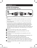
Make sure that the VGA and audio source is powered off.
2
Connect the VGA and audio source to the
INPUT
port(s) on the
transmitter unit using a VGA and audio cable.
3
(Optional – B132-004A-2 only) –
Connect a local monitor and
speakers to the
LOCAL
port(s) on the transmitter unit.
4
Connect the external power supply to the transmitter unit, then plug
it into a Tripp Lite Surge Protector, Power Distribution Unit (PDU) or
Uninterruptible Power Supply (UPS).
5
Using Cat5e/6 cable, connect an available RJ45
OUTPUT
port on
the transmitter unit to the RJ45
INPUT
port on a receiver unit (see
Product Features section for your model’s max distance information).
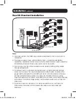
6
Repeat step 5 for each receiver unit you are connecting to the
installation.
7
(B132-100A-MR and B132-100A-SR)
– Connect the built-in VGA
cable to the monitor’s VGA port. Connect a 3.5 mm audio cable
between the receiver unit and the monitor or external speakers.
(B132-200A-SR)
– The B132-200A-SR features two sets of VGA
and audio ports. Connect each set of ports to a set of monitors and
speakers using VGA video and 3.5 mm audio cables.
8
(B132-100A-MR and B132-100A-SR)
– Use included Micro USB
cable to connect the receiver unit with a USB port on the monitor or
USB wall outlet.
(B132-200A-SR)
– Connect the external power supply to the receiver
unit, then plug it into a Tripp Lite Surge Protector, Power Distribution
Unit (PDU), or Uninterruptible Power Supply (UPS).
9
Repeat steps 7 and 8 for each receiver unit in the installation.
10
Turn on the power to the monitor and speakers.
11
Turn on the power to the VGA monitor and audio source.
12
If necessary, adjust the
equalization
and
gain
controls using the
included screwdriver to improve the video image.
Installation
continued
15-04-118-9333BE.indd 12
4/8/2015 10:35:10 AM


