background image

4

Standard Installation

Note:

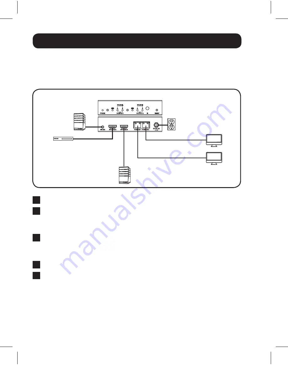
1.  The diagram below shows a B119-2X2 installation, but installation will be the same for the 

B119-4X4, except for the number of ports.

2.  The back panel of the B119-4X4 contains an IR port which has been capped off. This port is 

intended for future use, and does not currently function.

B119-2x2

(Optional)

Up to 25 ft.

Up to 16 ft.

Up to 16 ft.

Up to 25 ft.

Blu-Ray™

1

  Make sure all devices being connected are turned off.

2


Optional:

 Connect the 3.5 mm to DB9 adapter to the RS-232 serial 

port on the switch, and then to the DB9 serial port on the computer 

you will be using to control it with.

3

  Connect the first HDMI source to the port on the switch marked 

Source A


Note: 

The HDMI cable connecting the source to the switch must be no longer than 16 ft.

4

  Repeat step 3 to connect additional HDMI sources to the remaining ports.

5

  Connect the external power supply to the switch and plug it into 

a Tripp Lite Surge Suppressor, Power Distribution Unit (PDU), or 

Uninterruptible Power Supply (UPS). When receiving power, the 
following LEDs will illuminate: The Green 

Power

 LED and Orange 

Source

 LEDs (for the 

Source

 ports that have devices connected to 

them). A Green LED will also illuminate to indicate the source that is 
being transmitted to each 

Output

 port.

13-08-038-9332BC.indd   4

8/5/2013   12:26:37 PM

Summary of Contents for B119-2X2

Page 1: ...p Lite All rights reserved Package Contents 2 Product Features 2 Mounting 3 Standard Installation 4 RS 232 Serial Control 6 Troubleshooting 9 Warranty Warranty Registration 10 W ARR ANTY REGISTR ATIO...

Page 2: ...e same input to be routed to multiple outputs Switch between inputs via pushbuttons remote control or RS 232 serial Monitors can be located up to 25 ft from the switch Supports video resolutions up to...

Page 3: ...ow the different ways the included mounting brackets can be attached for different mounting methods Note The images below show a B126 1A1 HDMI over Cat5 Receiver Unit but the mounting hardware install...

Page 4: ...rt on the computer you will be using to control it with 3 Connect the first HDMI source to the port on the switch marked Source A Note The HDMI cable connecting the source to the switch must be no lon...

Page 5: ...Output LEDs to switch the source being displayed on the corresponding Output monitor You can also use the included remote control to switch between sources As with the switch next to the Output LEDs...

Page 6: ...oftware and update the COM port settings 1 Go to the Setup drop down menu and select the Serial Port option 2 Select the COM port that is being used and update the remaining settings as follows Baud R...

Page 7: ...gure your software to allow input control Go to the Setup drop down menu and select the Terminal option 4 Update the following settings Receive LF Local Echo enable The remaining settings can stay as...

Page 8: ...able commands Command Action sw x n Switches the source being displayed on the selected output x is the output 1 2 3 or 4 and n is the desired source A B C or D For example a command of sw1 2 would di...

Page 9: ...y are working properly For example connect your HDMI cables between a source and monitor that you know works to see if the cable is functioning 5 Is the switch located in an area that exposes it to hi...

Page 10: ...REGISTRATION Visit www tripplite com warranty today to register the warranty for your new Tripp Lite product You ll be automatically entered into a drawing for a chance to win a FREE Tripp Lite produc...

Page 11: ...the country Send the new equipment back for recycling when this ultimately becomes waste WARNING Use of this equipment in life support applications where failure of this equipment can reasonably be e...

Page 12: ...12 1111 W 35th Street Chicago IL 60609 www tripplite com support 13 08 038 93 32BC_revB 13 08 038 9332BC indd 12 8 5 2013 12 26 38 PM...

Reviews: