Tripp Lite B020-008-17 Owner'S Manual Download Page 21

21

8. Firmware Upgrade Utility

8.1 Before You Begin

To prepare for the firmware upgrade, do the following:
1.  From a computer that is not part of your KVM installation go to www.tripplite.com/support  

and choose the model name that relates to your device to get a list of available Firmware 

Upgrade Packages.

2.  Choose the Firmware Upgrade Package and Firmware Upgrade Utility you want to install 

(usually the most recent), and download it to your computer.

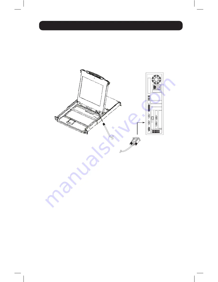
3.  Use the Firmware Upgrade Cable (provided with this unit), to connect a COM port on your 

computer to the Firmware Upgrade Port of your switch.

Note: 

On a daisy chained installation, the chained stations will automatically receive the upgrade via the 

daisy chain cables.

4.  Shut down all of the computers - but not the daisy-chained KVM Stations - on your KVM 

installation.

5.  From your KVM switch console, bring up the OSD (see pages 14-20) and select the

 F4 ADM


function.

6.  Scroll down to 

FIRMWARE UPGRADE

. Press

 [Enter]

, then press

 [Y]

 to invoke Firmware 

Upgrade Mode. For your reference, the current firmware upgrade version displays on the 
screen.

14-08-026-933077.indd   21

9/9/2014   11:25:43 AM

Summary of Contents for B020-008-17

Page 1: ...surge protector a 50 value www tripplite com warranty 1111 W 35th Street Chicago IL 60609 USA www tripplite com support Copyright 2014 Tripp Lite All rights reserved All trademarks are the property o...

Page 2: ...9 Configuration 6 Hotkeys 10 6 1 Port Selection 10 6 2 Port Control Using Hotkeys 10 6 3 Invoking the Hotkey Mode 10 6 4 Port ID Numbering 11 6 5 Selecting the Active Port 11 6 6 Auto Scanning 11 6 7...

Page 3: ...oard and mouse or IP interface unit connection capability 2 1 Computer A VGA SVGA or Multisync computer with a HD15 port Note The B020 016 17 and B020 008 17 have a maximum resolution of 1280 x 1024 s...

Page 4: ...s The LED is steady under normal conditions but flashes when its port is accessed under Auto Scan Mode see page 11 6 Keyboard 7 Touchpad 8 Power LED Lights BLUE to indicate that the unit is receiving...

Page 5: ...empt to use ordinary 15 pin VGA connector cables to link these ports to the computers 3 Power Socket This is a standard 3 prong AC power socket The power cord from an AC source plugs in here 4 Power S...

Page 6: ...itch is designed for mounting in a 1U rack system The various mounting options are explained in the sections that follow Standard Rackmounting The standard rackmounting brackets that come attached to...

Page 7: ...ust be followed Hot Plugging CPU Ports Switch CPU ports by unplugging the KVM cable kit and replugging into the desired port In order for the OSD menus to correspond to the change made you must manual...

Page 8: ...se it by pushing the catches on the unit s front panel toward the center of the switch 5 2 Closing the NetDirector Console KVM To slide the console module back in close the cover and do the following...

Page 9: ...siders optimal Brightness Adjusts the background black level of the screen image Contrast Adjusts the foreground white level of the screen image Phase Adjusts the vertical size of the screen image Clo...

Page 10: ...g the Hotkey Mode To initiate the Hotkey Mode Press and hold down the Num Lock key Press and release the Minus key or Asterisk key Release the Num Lock key Note 1 The or key must be released within on...

Page 11: ...ong number 2 Press Enter Once Enter has been pressed the KVM switches to the designated computer and you automatically exit the Hotkey Mode 6 6 Auto Scanning When in the Auto Scan mode the KVM automat...

Page 12: ...ular port for as long as you like To invoke Previous Next Switching key in the following Hotkey combination 1 Invoke Hotkey Mode with the Num Lock combination 2 Key in Arrow refers to any of the arrow...

Page 13: ...ble port previous to it g Invokes Skip Mode and skips from the current port to the next accessible port h Invokes Skip Mode and skips from the current port to the last accessible port of the previous...

Page 14: ...appears Note 1 The diagram depicts the Administrator s Main Screen The User Main Screen does have the F4 and F6 functions since they can t be accessed by ordinary Users and are reserved for the Admini...

Page 15: ...use the Name enter 1 key in the port s Name then press Enter To use the Port ID enter 2 key in the Port ID then press Enter Note A partial Name or Port ID can be entered The screen will show all the c...

Page 16: ...sec Always On displays the Port ID at all times If choosing User Defined key in the number of seconds and press Enter The default is 3 Seconds A setting of 0 zero disables this function PORT ID DISPLA...

Page 17: ...Operators access the computers if the original has forgotten to log out To set the timeout value key in a number from 1 180 minutes then press Enter If the number is 0 zero this function is disabled...

Page 18: ...blank Repeat until all access rights have been set then press Enter The default is V for all users on all Ports Note A blank setting means that access rights have not been granted The Port will not a...

Page 19: ...only keys you will be able to use are the arrow keys The Skip Mode must be exited in order to regain normal control of the keyboard and mouse To exit Skip Mode press Esc or Spacebar F6 Broadcast Mode...

Page 20: ...is being accessed under Auto Scan Mode While Auto Scan Mode is in effect the keyboard and mouse will not function You must exit Auto Scan Mode in order to regain control of the console While in Auto...

Page 21: ...rmware Upgrade Cable provided with this unit to connect a COM port on your computer to the Firmware Upgrade Port of your switch Note On a daisy chained installation the chained stations will automatic...

Page 22: ...ices a detailed description of each appears in the Device Description panel 5 After you have made your selection s click Next to perform the upgrade If you enabled Check Firmware Version the Utility c...

Page 23: ...e Firmware Upgrade Utility 8 4 Upgrade Failed If the upgrade failed to complete successfully a dialog box appears asking if you want to retry Click Yes to retry If you click No the Upgrade Failed scre...

Page 24: ...the switch Note Unplug the power cord of any computer that has the Keyboard Power On function Otherwise the KVM will still receive power from this computer 2 Wait 10 seconds then plug the KVM switch...

Page 25: ...Green 16 Green Power LED Blue Station ID N A Console Connectors HD15 F Monitor PS 2 F Mouse PS 2 F Keyboard CPU Ports 8 HD15 F 16 HD15 F Required Cable Kits Sold Separately P774 Series PS 2 P776 Serie...

Page 26: ...interference that may cause undesired operation Note This equipment has been tested and found to comply with the limits for a Class A digital device pursuant to part 15 of the FCC Rules These limits a...

Page 27: ...lusion s may not apply to the purchaser Except as provided above in no event will Tripp Lite be liable for direct indirect special incidental or consequential damages arising out of the use of this pr...

Page 28: ...28 1111 W 35th Street Chicago IL 60609 USA www tripplite com support 14 08 026 93 3077_revB 14 08 026 933077 indd 28 9 9 2014 11 25 46 AM...

Reviews: