background image


                                          12                                  


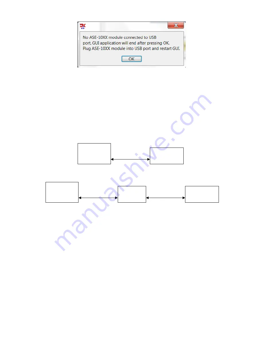
Figure 5.2-2 - Error Message Displayed When ASE-1019 is Not Connected to USB Port


6.0


Ethernet Based Control/Status Setup and Initial Power-On 

An external computer with a 10/100BaseT Ethernet port is required to provide control and status 
for the ASE-1019 module using a standard HTML browser (Chrome, Firefox, Internet Explorer) 
based GUI.  When using Ethernet communications to control/status the ASE-1019 module, there is 
no other special software required, the browser (Chrome, Firefox, Internet Explorer) is sufficient. 
 
There are two primary ways to configure the hardware connection between the external computer 
and the ASE-1019 module, both are shown in Figure 6.0-1.  Use the included Ethernet cable and 
setup the hardware connection in either of the two ways shown in the figure.     


10/100BaseT

Ethernet Cable

10/100BaseT

Ethernet Cable

10/100BaseT

Ethernet Cable

External

Computer

with Browser

ASE-1019

Module

OR

(direct connection)

External

Computer

with Browser

Ethernet

Router

ASE-1019

Module


Figure 6.0-1 - Two Methods of Using an Ethernet Interface to the ASE-1019 Module  

Provide power to the module by plugging the +5V AC/DC adapter into a standard 120 VAC wall 
outlet then into the module’s DC port.  The LED on the top side of the module should illuminate to 
a green color indicating that DC power is being supplied to the module.  If the LED does not 
illuminate, it is an indication that DC power is not being supplied to the module.  

6.1


Initial Setup for Ethernet Control/Status 

The ASE-1019 module is shipped in Static IP address mode to allow communication via a direct 
connection to a standalone computer as shown in the upper block diagram of Figure 6.0-1.  In 
order to initially communicate with the ASE-1019, setup the Ethernet port of the standalone 
computer as given in Table 6.1-1. 

Summary of Contents for ASE-1019

Page 1: ...Triple Play Communications Document 3013800 701 250 East Drive Suite F Rev 1 1 Melbourne FL 32904 July 2015 1 ASE 1019 ASE Light Source ASE 1019 ASE Light Source User s Manual...

Page 2: ...2 Revision History Document Revision Date Description 1 0 Feb 2015 Initial Release 1 1 July 2015 Updated several GUI images of optical control status...

Page 3: ...odule and Initial Power On 11 6 0 Ethernet Based Control Status Setup and Initial Power On 12 6 1 Initial Setup for Ethernet Control Status 12 6 2 IP Address Reset Button on bottom side of module 14 7...

Page 4: ...1 1 Critical Status Area of the Main Menu in both dBm and Watts 16 Figure 7 2 2 1 Key Control Functions on the Main Menu 16 Figure 7 2 2 2 ACC Mode with a User Entered Setting of 475 mA for the Bias...

Page 5: ...ort Setup for Operation with Ethernet Router Using Static IP 13 Table 6 1 3 ASE 1019 Ethernet Port Setup for Operation with Ethernet Router Using Dynamic IP14 Table 8 3 1 Ethernet Configuration Descri...

Page 6: ...r is provided to power the module In addition to the Ethernet GUI the ASE 1019 can be connected directly to a Windows based computer which runs the USB graphical user interface GUI software This GUI a...

Page 7: ...hout changing any parameters if desired Table 2 1 1 Default Operational Settings as Shipped from the Factory Control Function Default Setting Description Bias Current 450 mA Set for advertised output...

Page 8: ...FR 1040 10 and 1040 11 International safety standards for lasers and laser amplifiers are described in the IEC 60825 1 2007 document 4 2 Class 1M Source of Optical Radiation The ASE 1019 delivers invi...

Page 9: ...st caps should always be left on the connectors when not in use These dust caps not only keep the connectors clean but they also protect the user from any optical radiation that may emanate from these...

Page 10: ...ly 4 minutes the small window shown in Figure 4 1 3 will appear to indicate the installation process is in progress 4 Once installation is complete the window in Figure 4 1 4 will be shown to remind t...

Page 11: ...module with the typical Windows USB connection sound Open the GUI application by clicking on the Windows Start icon All Programs TPC folder and finally the ASE_10XX application The GUI will open and...

Page 12: ...ernet Cable 10 100BaseT Ethernet Cable 10 100BaseT Ethernet Cable External Computer with Browser ASE 1019 Module OR direct connection External Computer with Browser Ethernet Router ASE 1019 Module Fig...

Page 13: ...19 module to an Ethernet router for remote control and status setup the module as described in Table 6 1 2 if a Static IP address is desired or as described in Table 6 1 3 if a Dynamic IP address is d...

Page 14: ...e The second is to connect to the USB port of the module and open the USB GUI Click on the Device Info box and the Device Information window will display the current IP address 6 Using a computer whic...

Page 15: ...creen by clicking the bar at the top of the window and dragging it to a different location The size of this window cannot be changed By clicking on Device Info a new window is opened to show specific...

Page 16: ...the output power monitor will display 35 dBm A temperature sensor is mounted on the PCB and its value in degrees Celsius is continuously updated on the display 7 2 2 Primary Control Functions The key...

Page 17: ...fic bias current to the amplifier as shown in Figure 7 2 2 2 The internal amplifier has a bias current setting accuracy of 10 so the bias current displayed in the main menu can have a variation of up...

Page 18: ...ts internal microcontroller s firmware Standard HTML browsers such as Chrome Firefox and Internet Explorer can be used to provide control and status of the module After completing the Ethernet port se...

Page 19: ...nd displayed in prominently in the upper area of this window The total optical output power is monitored using a 1 tap to minimize insertion loss The calculated value is displayed in its designated lo...

Page 20: ...the user must enter the target bias current setting which ranges from 0 mA to the Bias Current Limit shown in the second row of status Once the user types in the target bias current and presses Enter...

Page 21: ...ower The user can manually Enable or Disable the amplifier output with the dropdown menu in the fourth row of the control functions as shown in Figure 8 1 1 6 Whenever the user selects Disable the amp...

Page 22: ...ndow as well as in the LED located on the top side of the module The Module Fault Status is a logical OR of several alarms which are laser bias current exceeds the maximum current limit laser pump tem...

Page 23: ...the module is pressed the Ethernet mode and IP address will be reset to this default configuration Figure 8 3 1 Ethernet Setup Controls with Factory Default IP Address The Ethernet Mode can be set to...

Page 24: ...a Static address this field is used to enter the full IP Subnet If Dynamic is selected this field is not used xxx xxx xxx xxx IP Gateway If the Ethernet port is configured as a Static address this fie...

Page 25: ...the user must close the browser window by clicking the X in the upper right hand corner of the browser wait 30 seconds for the chassis to reboot then open a new browser window to restart communicatio...

Page 26: ...m Output Return Loss 35 dB Output Optical Isolation 40 dB Power Stability after 60 minute warm up 0 1 dB 0 1 dB The ASE 1019 output spectrum shown below with no gain flattening filter shows the module...

Page 27: ...AC DC Adapter Operating Current 740 mA 800 mA Ethernet Communications Interface1 10 100BaseT USB Communications Interface USB 2 0 Ethernet User Interface ex Chrome Firefox IE HTML Browser USB User Pla...

Page 28: ...ring Description Part Number ASE 1019 ASE Light Source ASE 1019 Includes Gain Flattening Filter G No Gain Flattening Filter N C band C USB and Ethernet control status interface E Data logging D No Dat...

Reviews: