


IDX 7505 Manual (V1.17 / 2011-APR-11)
22
Copyright © 2011, TRINAMIC Motion Control GmbH & Co. KG
c)
if the distance to the power supply is large (i.e. more than 2-3m), use a robust 4700µF or
similar additional filtering capacitor located near to the motor driver unit. Choose the
capacitor voltage rating fitting to the maximum operating voltage.
The overall power rating mainly depends on the motor used and on the mechanical output power,
i.e. the motor velocity and desired torque. As a thumb rule, a 42mm class motor will require a 10W
(short motor) to 20W (long motor) power supply, while a 57mm motor will require 15W to 30W,
when operated at maximum rated current and low velocities. Operation at very high velocities will
increase the power demand up to the double value.
6.3.1
EMV considerations
Due to the small form factor of the unit, it is not completely protected against electromagnetic
emissions resulting from switching operation. If your system is subject to CE testing and shows EMV
problems, i.e. due to some parts of the housing/cabling not being shielded, provide ferrite filters for
the positive power supply line and for the motor outputs near to the unit. A 470pF to 1nF (100V)
capacitor to GND then should be added externally to each ferrite filter.
6.4
Connections for step/dir mode
The step-direction-mode is enabled if the acceleration is set to 0 (default) using the RS485 interface.
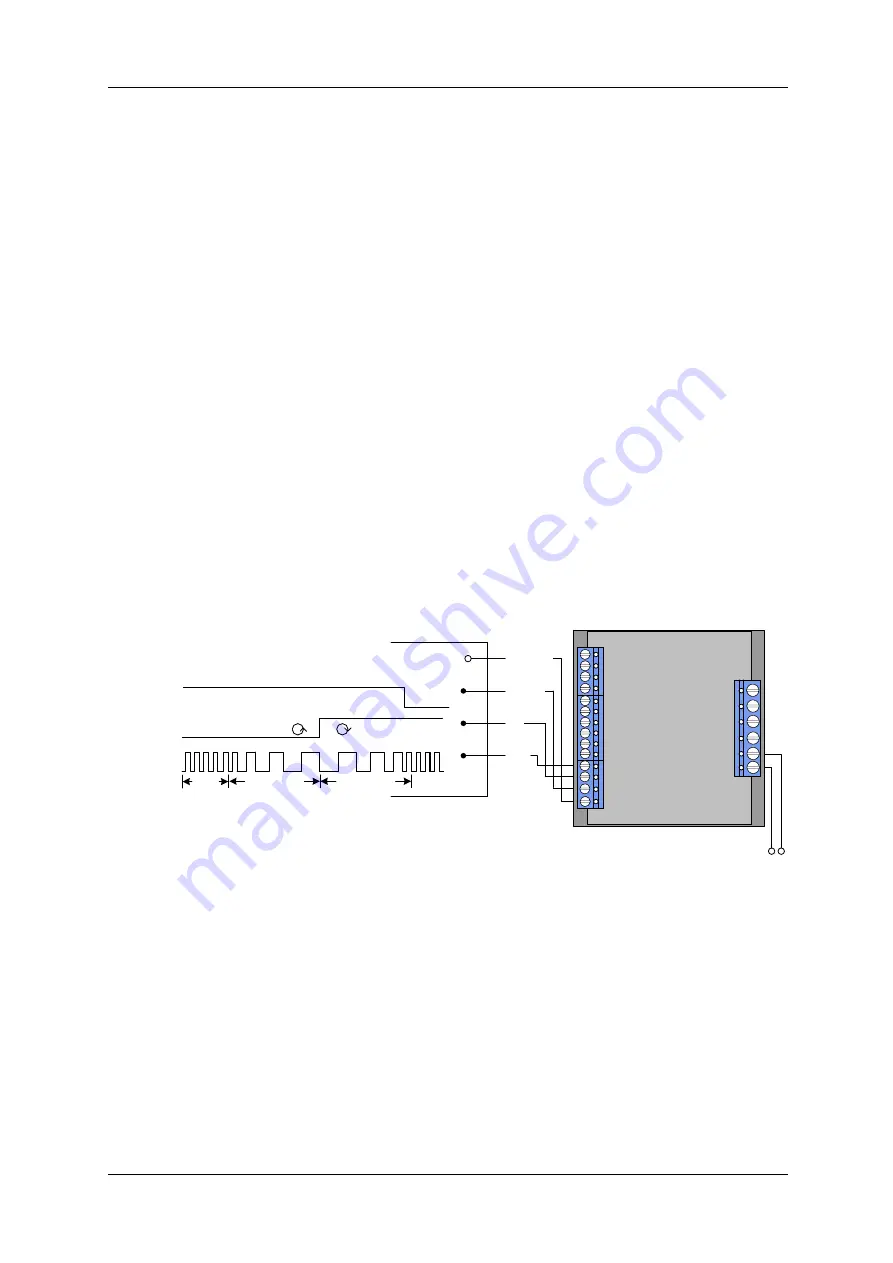
The example input signals of Figure 6.3 are schematically (see chapter 5.2 for more information):
Dir
Common
Disable
Step
PWR 12… 50V
TMCM IDX
5… 24V
Dir
Common
0V
rotating direction
Disable
Common
0V
rotation on off
at V
common
or left open
Step
Common
0V
Velocity Deceleration Acceleration
const.
Figure 6.3: Contacts for step/dir
The maximum step frequency is 350 kHz (limited by the optocouplers).
6.5
Connections for RS485 interface
The RS485-mode allows for configuration of motor parameters as well as remote control of the
motor.


