background image

17

ASSeMBLiNg THe BOiLer

Circulator wiring

SUPPLIED JUMPERS

AQUASTAT CONTROL HARNESS

120 VAC POWER

BURNER HARNESS

Figure 11 - Control Box Wiring

!


WARNING

Ensure all conduit is secured to prevent contact with flue pipe.

Summary of Contents for UB4TRA075

Page 1: ...ev D 1 09 TriFire High Efficiency Oil Fired Hot Water Boiler INSTALLATION OPERATION MAINTENANCE MANUAL MEMBER The Hydronics Institute Utica BOILERS P O Box 4729 Utica NY 13504 4729 R An ISO 9001 2000 Certified Company ...

Page 2: ...boiler is a natural draft oil fired hot water boiler comprised of cast iron sections The boiler is available with 4 5 6 or 7 cast iron sections These sections are held together by push nipples and threaded rods The boiler family is capable of firing 2 fuel oil from 0 75 gph up to 1 65 gph All packaged boilers include a Honeywell aquastat temperature and pressure gauge 30 psi relief valve and drain...

Page 3: ...th skin Wash affected area gently with soap and water Seek immediate medical attention if irritation persists If breathing difficulty develops Leave the area and move to a location with clean fresh air Seek immediate medical attention if breathing difficulties persists If Ingestion occurs Do not induce vomiting Drink plenty of water Seek immediate medical attention WARNING This product contains re...

Page 4: ...The Boiler 13 Equipment And Accessories 18 Boiler System Piping 20 Piping Diagrams 21 Fuel Oil Piping 33 Antifreeze In The System 34 Electrical Connections 35 Chimney And Chimney Connections 37 Operating The Boiler System Start Up 40 Oil Burner Nozzle Air Settings 46 Maintenance 49 Oil Boiler Burner Cleaning Instructions 51 Oil Burner Cleaning 52 Troubleshooting 53 TABLE OF CONTENTS ...

Page 5: ...lation practices All wiring on boilers installed in Canada shall be made in ac cordance with the Canadian Electrical Code C22 2 and or local regulations The following terms are used throughout this manual to bring atten tion to the presence of hazards at various risk levels or to important information concerning product life These symbols are based on ANSI Z535 6 standard for product literature WA...

Page 6: ...stallation on combustible flooring Do not install boiler on carpeting Do not tamper with or alter the boiler or controls Inspect flue ways at least once a year Preferably at the start of the heating season The inside of the combustion chamber the vent system and boiler flue ways should be cleaned if soot or scale has accumulated When cleaning this boiler take precaution to avoid damage to burner s...

Page 7: ... the expansion tank s air charge will need to be increased to match the fill pressure Consult the expansion tank manufacturer s guidelines for sizing and selection Purging the heating system of air and gases when first putting 11 the boiler into service is critical for proper circulation and quiet performance Once the air is purged for boiler installations using float type vents the air vents shou...

Page 8: ...m the system piping The Net I B R Ratings shown are based on a piping and pickup factor of 15 in accordance with the I B R Standard as published by the Hydronics Institute The Net I B R Rating of the boiler selected should be greater than or equal to the calculated peak heating load heat loss for the building or area s served by the boiler and associated hot water heating systems The manufacturer ...

Page 9: ...4 24 1 8 17 3 4 7 34 1 4 27 1 2 17 3 4 Locating The Boiler TABLE 2B BOILER CLEARANCES Unit Combustible Clear ance Accessibility Cleaning and Servicing Top 12 24 Right Side 2 24 Left Side 2 24 Floor Combustible No Requirement Front 17 24 Back See Flue 18 All distances measured from the boiler jacket or flue For minimum clearances to combustible materials see 6 Figure 1 and Table 2B Fresh air fo 7 r...

Page 10: ...10 Installation Requirements Figure 2 General Requirements for a typical installation NOTICE Always keep the manual fuel supply valve shut off if the burner is shut down for an extended period of time ...

Page 11: ...space Duct cross sec tional area shall be same as opening free area Fresh Air For Combustion Horizontal Ducts c Minimum free area of 1 square inch per 2 000 BTU per hour input of all equipment in space Duct cross sectional area shall be same as opening free area Alternate method for boiler located within confined space Use indoor air if two permanent openings communicate directly with additional s...

Page 12: ... DUCT CAPACITIES Through Louvers Fresh Air Duct Size Mesh Screen Wood Louvers Metal Louvers Btuh Btuh Btuh 3 x 12 144 000 36 000 108 000 8 x 8 256 000 64 000 192 000 8 x 12 384 000 96 000 288 000 8 x 16 512 000 128 000 384 000 Btuh British Thermal Units per hour based on opening covered by mesh screen wood louvers or metal louvers Figure 2B ...

Page 13: ...ounting bracket holes Inspect Swing door insulation and rope gasket 5 Inspect fiber rope located on the swing door The rope must A be evenly distributed around the perimeter of the door groove and cannot bunch or overhang There must not be a gap where the two ends of the rope meet Repair or replace if the rope is damaged or if there is a gap between the ends Inspect burner swing door insulation fo...

Page 14: ...CO Install sensor in well in top of last section of boiler Force sensor to bottom of well and secure with clip See Figure 3A Figure 4 Install Relief Valve 16 Refer to Figure 5 Locate 3 4 NPT x 90 elbow Install elbow using 3 4 NPT A boss on rear of control manifold Elbow must be installed with outlet facing directly up Install relief valve with outlet facing either horizontally right or left of boi...

Page 15: ... CONTROLS MANIFOLD PORT SCHEDULE Port Port Size Description A 1 4 NPT Temperature Pressure Gauge B 3 4 NPT Low Water Cut Off Optional C 1 2 NPT High Temperature Limit Manual Reset Optional D 3 4 NPT Relief Valve E 3 4 NPT Aquastat Control Mounting Plug Figure 6 All Optional Accessories Shown WARNING No valves may be installed between boiler and controls manifold or safety relief valve ...

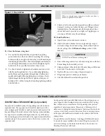
Page 16: ...nstalled See Figure 11 Connect the wiring harness from the Aquastat to the circula C tor See Figure 10 120 volt power supply field wiring will enter through jacket D rear panel Wire the power supply as shown in E Figure 11 Connect the green wire to the grounding lug When installing the wiring through the hole in the control panel be sure to use an anti abrasion cable clamp Connect black hot wire t...

Page 17: ... WHITE BLACK TO YELLOW GREEN TO GROUND SCREW Circulator wiring SUPPLIED JUMPERS AQUASTAT CONTROL HARNESS 120 VAC POWER BURNER HARNESS Figure 11 Control Box Wiring WARNING Ensure all conduit is secured to prevent contact with flue pipe ...

Page 18: ...Use a hand wrench to tighten door hardware and always start B with the non hinged side first Use an alternating tightening method from non hinged side to hinged side to tighten door equally until sealed without applying excessive torque Never tighten hinged side flange bolt first or tighten either piece of hardware 100 without using the alternating tightening method described above CONVENTIONAL EX...

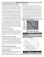
Page 19: ...d and simplify this process The main air vent should be installed on the highest point in the sup ply main AUTOMATIC FILL VALVE not provided For safe efficient operation a hot water system must be filled with water Adding new water when needed can be done manually by use of a hand valve in the water supply line This requires regular attention to the system s needs An automatic fill valve or pressu...

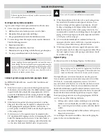
Page 20: ...circulating pump on the supply side piping such that it pumps away from the expansion tank Refer to the figures on the next pages A hot water 5 boiler installed above radiation level must be equipped with a low water cut off device A periodic inspection is necessary per manufacturers specific instructions When connecting the cold water supply 6 to the pressure reduc ing valve make sure that a clea...

Page 21: ...tect the boiler from sustained condensing operation for low temperature applications such as radiant floor heating These types of system require active controls that prevent the return of cold return water to the boiler Consult your local heating specialist In addition refer to the Radiant Panel Association RPA www radiantpanelassociation org for piping recommendations for non condensing boiler ap...

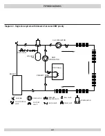
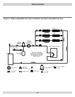
Page 22: ...E CIRCULATOR EXPANSION TANK WATER INLET FLOW CONTROL VAVLE SHUT OFF VALVE PRESSURE REDUCER VALVE CHECK VALVE BALL VALVE AIR SEPARATOR ZONE VALVE HOSE BIB PIPING DIAGRAMS 22 DHW Heater Diagram 2 Single Zone system with domestic hot water DHW priority ...

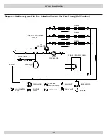
Page 23: ...IMUM TANK PERFORMANCE CONSIDER USING ZONE CIRCULATOR SEE FIGURE 5 ZONE 4 CIRCULATOR SHUT OFF VALVE PRESSURE REDUCER VALVE CHECK VALVE EXPANSION TANK AIR SEPARATOR ZONE VALVE HOSE BIB FLOW CONTROL VALVE PIPING DIAGRAMS 23 Diagram 3 Multizone Piping With Zone Valves And Domestic Hot Water Priority With Zone Valve ...

Page 24: ...LVE DHW CIRCULATOR CH CIRCULATOR CIRCULATOR FLOW CONTROL VALVE SHUT OFF VALVE PRESSURE REDUCER VALVE CHECK VALVE BALL VALVE AIR SEPARATOR ZONE VALVE HOSE BIB EXPANSION TANK PIPING DIAGRAMS 24 Diagram 4 Multizone System With Zone Valves And Domestic Hot Water Priority With Circulator ...

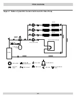
Page 25: ...ATER INLET CIRC 2 CIRC 3 CIRC 4 CIRCULATOR SHUT OFF VALVE PRESSURE REDUCER VALVE CHECK VALVE BALL VALVE AIR SEPARATOR ZONE VALVE HOSE BIB FLOW CONTROL VALVE EXPANSION TANK PIPING DIAGRAMS 25 Diagram 5 Multizone System With Circulators And Domestic Hot Water Priority ...

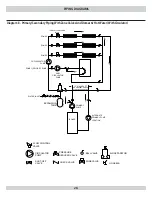
Page 26: ...O PREVENT FORCED FLOW IN SECONDARY ZONE 4 DHW PUMP CIRCULATOR PUMP SHUT OFF VALVE PRESSURE REDUCER VALVE CHECK VALVE BALL VALVE AIR SEPARATOR ZONE VALVE HOSE BIB FLOW CONTROL VALVE EXPANSION TANK WATER INLET PIPING DIAGRAMS 26 Diagram 6 Primary Secondary Piping With Circulators And Domestic Hot Water ...

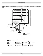
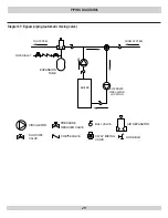
Page 27: ...ON ZONE 4 USE FULL PORT ZONE VALVE FOR OPTIMUM TANK PERFORMANCE CONSIDER USING ZONE CIRCULATOR SEE FIGURE 13 CIRCULATOR SHUT OFF VALVE PRESSURE REDUCER VALVE CHECK VALVE BALL VALVE AIR SEPARATOR ZONE VALVE HOSE BIB FLOW CONTROL VALVE EXPANSION TANK PIPING DIAGRAMS 27 Diagram 7 Primary Secondary Multizone System Piping With Zone Valves And Domestic Hot Water With Zone Valve ...

Page 28: ...ZONE 4 USE FULL PORT ZONE VALVE DHW CIRCULATOR PUMP CH CIRCULATOR PUMP WATER INLET CIRCULATOR PUMP SHUT OFF VALVE PRESSURE REDUCER VALVE CHECK VALVE BALL VALVE AIR SEPARATOR ZONE VALVE HOSE BIB FLOW CONTROL VALVE EXPANSION TANK PIPING DIAGRAMS 28 Diagram 8 Primary Secondary Piping With Zone Valves And Domestic Hot Water With Circulator ...

Page 29: ...CULATOR LOCATION TO SYSTEM FROM SYSTEM CIRCULATOR SHUT OFF VALVE PRESSURE REDUCER VALVE CHECK VALVE BALL VALVE 3 WAY MIXING VALVE AIR SEPARATOR HOSE BIB EXPANSION TANK PIPING DIAGRAMS 29 Diagram 9 Bypass piping automatic mixing valve ...

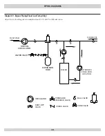
Page 30: ... SHUT OFF VALVE PRESSURE REDUCER VALVE CHECK VALVE BALL VALVE AIR SEPA ZONE VALVE EXPANSION TANK WATER INLET SYSTEM CIRCULATOR PIPING DIAGRAMS 30 Adjust the two throttling valves to maintain at least 130 F 140 F in the boiler return Diagram 9 Bypass Piping Fixed Low Temp Only ...

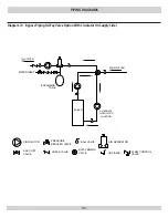
Page 31: ...TEM CIRCULATOR WATER INLET SHUT OFF VALVE PRESSURE REDUCER VALVE CHECK VALVE BALL VALVE AIR SEPARATOR HOSE BIB FLOW CONTROL VALVE 4 WAY MIXING VALVE EXPANSION TANK PIPING DIAGRAMS 31 Diagram 10 Bypass Piping 4 Way Valve Option With Circulator On Supply Side ...

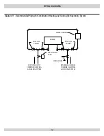
Page 32: ...OFF VALVES BOILER SUPPLY MAIN TO COMBINED HEATING COOLING SYSTEM RETURN MAIN FROM COMBINED HEATING COOLING SYSTEM CIRCULATOR WATER CHILLER AIR CUSHION TANK Diagram 11 Recommended Piping for Combination Heating and Cooling Refrigeration System ...

Page 33: ...burners are delivered as single stage single pipe 1 installation with the bypass plug removed The single stage fuel unit may be installed single pipe with 2 gravity feed or lift Maximum allowable lift is 8 feet See Figure 14 Fuel Oil Line Deaerator On many occasions a leaky oil delivery 3 line can introduce air into the fuel oil supply system This often creates a rough starting condition and can c...

Page 34: ...umber of Boiler Section Total Volume Gallons 4 3 6 5 4 3 6 5 1 7 5 9 TABLE 7 PIPING WATER VOLUMES PIPE SIZE COPPER PIPE FACTOR STEEL PIPE FACTOR 82 5 63 5 40 0 36 0 1 23 3 22 2 1 15 3 12 8 1 10 8 9 5 2 6 2 5 8 Divide total length of piping in feet by appropriate factor in table to determine volume in gallons TABLE 5 TWO STAGE UNITS TWO PIPE SYSTEMS SEE FIGURE 15 LIFT H Maximum Length of Tubing R 3...

Page 35: ...is turned off WARNING Failure to properly wire electrical connections to the boiler may result in serious physical harm Electrical power may be from more than one source Make sure all power is off before attempting any electrical work Each boiler must be protected with a properly sized fused disconnect Never jump out or make inoperative any safety or operating controls 35 Electrical Connections Fi...

Page 36: ...36 ELECTRICAL CONNECTIONS Figure 18 Wiring Diagram 240007363 All Models Optional Equipment Shown ...

Page 37: ...from type L vent or a factory built chimney that complies with the type HT requirements of UL103 See Figure 20 for recommended installation Chimney Inspection Prior to the installation of any new or 4 replacement fuel burning equipment the chimney shall be in spected by a qualified installer The chimney shall be examined by a qualified person in accordance with the requirements of NFPA 211 Standar...

Page 38: ...ring the draft Minimum Draft at Breech The draft induced by a chimney 2 must create at least a pressure of 0 zero inches water column INWC at the breach The pressure at the breach cannot be positive since this could create a condition that allows flue gas by products to escape from the draft regulator Draft is to be measured up stream of the draft regulator See the Burner Specifications section at...

Page 39: ...39 CHIMNEY AND CHIMNEY CONNECTIONS Figure 19 Proper Draft Vent Locations Figure 20 Typical Chimney Locations 1 4 NPT TEST PORT FOR OVERFIRE MEASUREMENT Figure 21 Pressure Tapping for Checking Draft ...

Page 40: ... open all zone valves Close purge valve continue filling the system until the pressure H gauge reads 12 psi Close shut off valve in cold water supply piping WARNING The maximum operating pressure of this boiler is posted on the ASME Data Label located on the front lower leg of the boiler Never exceed this pressure Do not plug relief valve Open full port valve in boiler system piping I Remove hose ...

Page 41: ...part of normal operation The controller will enter the Error state when there is an abnormal condition The operating states are Normal Boiler temperature has dropped below the high limit setting minus the differential and has not exceeded the high limit setting High Limit Boiler temperature has risen above the high limit setting and has not dropped below the high limit setting minus the differenti...

Page 42: ...ng a fuel unit s operating pressure a reliable pres I sure gauge may be installed in either the bleeder port or the nozzle port Locate oil pressure adjusting screw and turn screw to obtain II proper pump pressure refer to Burner Settings section of this manual To check the cut off pressure deadhead a reliable pressure III gauge onto the copper connector tube attached to the nozzle port Run the bur...

Page 43: ...tion or carry over periods Limited Recycle III This feature limits the number of recycle tri als for each call for heat to a maximum of three trials If the flame is lost three times and does not successfully satisfy a call for heat the R7184 locks out Limited Reset IV Restricted Mode In order to limit the accumulation of unburned oil in the combustion area the control can only be reset three times...

Page 44: ...D Figure 23 Perform cad cell resistance check as outlined in control feature I If resistance is below 1600 OHMS and burner runs beyond safety cut out time cad cell is good If safety switch shuts down burner and resistance is above 1600 II OHMS turn on power to the boiler Access cad cell under igniter clean face of cad cell and see that cell is securely in socket Check gasket around perimeter of ig...

Page 45: ...in a smoke reading showing a trace smoke reading Once the smoke read ing is a trace measure the CO2 and as an insurance margin increase the air to sufficiently reduce the CO2 by 1 2 to 1 If a clean fire cannot be obtained it will be necessary to verify B the burner head alignment If the fire continues to be smoky replace the nozzle Once the burner is completely adjusted the burner should be C star...

Page 46: ...4 Beckett AFG Burner Electrode Adjustments Variable V1 L1 Heads Figure 1 Beckett AFG Variable V1 Head Adjustments and Settings NOTICE All burners use an insertion depth of 2 5 8 and fired at a breech draft of 0 05 to 0 00 inches W C The burner settings provided are intended for initial start up only Final adjustment must be made using combustion test instruments ...

Page 47: ... 2 Timings fixed Nozzle designations D DELAVAN H HAGO F DANFOSS Pre purge 15 seconds Post Purge 15 seconds TABLE 14B BECKETT NX DIRECT VENT BURNER SETTINGS BOILER SIZE MODEL NO HEAD AIR TUBE INSERT DEPTH FIRING RATE GPH PUMP PRESSURE PSIG NOZZLE MNF NOZZLE RATE NOZZLE MNF ALT NOZZLE RATE PRES SWITCH INWC AIR HEAD SETTING 4 NX NX1 NX70LC 2 675 0 75 150 D 0 60 X 70B D 0 60 X 70W 0 65 1 5 5 NX NX1 NX...

Page 48: ...designations D DELAVAN H HAGO F DANFOSS Pre purge 12 seconds Post Purge Electric air shutter TABLE 14D RIELLO 40BF DIRECT VENT BURNER SETTINGS BOILER SIZE MODEL NO HEAD TYPE INSERT DEPTH FIRING RATE GPH PUMP PRESSURE PSIG NOZZLE MNF NOZZLE RATE NOZZLE MNF ALT NOZZLE RATE AIR HEAD SETTING AIR SHUT SETTING PRES SWITCH INWC 4 40BF3 REVERSE 2 75 0 75 150 D 0 65 X 60B D 0 60 X 60B 3 5 0 25 5 40BF5 STD ...

Page 49: ...ection DIAPHRAGM EXPANSION TANK As noted in the EQUIPMENT AND ACCESSORIES section WATER SYSTEM If the system is to remain out of service during freezing weather always drain it completely water left in the system will freeze and crack the pipes and or boiler Maintenance OIL BURNER MAINTENANCE For the Beckett AFG the following preventative maintenance items should be performed annually preferably p...

Page 50: ...n the boiler to a level below the relief valve tapping B Remove relief valve using extreme care to avoid damaging it C Add an appropriate amount of recommended boil out com D pound Replace relief valve E Fill the entire system with water and purge F Start firing the boiler G Circulate the water through the entire system H Vent the system including the radiation I Allow boiler water to reach operat...

Page 51: ... damaged replace as needed Re assemble the boiler 4 Insert the liner and baffles if equipped into the correct flue A way The baffles are installed in the 3rd pass Two inner flue ways Inspect the chimney and clean if necessary B Clean and re attach the vent connector onto the rear of the C boiler with three screws Tighten swing door hardware to provide adequate seal to rope D gasket around perimete...

Page 52: ...nected to a dirty or inadequate chimney The interior of the chimney flue must be inspected and cleaned before the start of the heating season and should be inspected periodically throughout the heating season for any obstructions A clean and unobstructed chimney flue is necessary to allow noxious fumes that could cause injury or loss of life to vent safely and will contribute toward maintaining th...

Page 53: ...e fuel lines Shut down noise Post Purge timed 15 seconds should elimi H nate shut down noise OIL PRIMARY CONTROL 2 Burner control will not come on A No power to control I Control is in lockout or restricted mode Press reset button II for 30 seconds to exit lockout If control has recycled three times within the same call for heat it will enter into restricted mode To reset from restricted mode refe...

Page 54: ...on and or deposits on seat Open valve manually Allow water to run and clear valve seat Water logged expansion tank Drain tank follow instructions to provide air buffer HAVE YOUR SERVICE TECHNICIAN CHECK ANY PROBLEM YOU ARE UNABLE TO CORRECT Aquastat Troubleshooting Guide System Condition Diagnostic Condition Check Action Boiler is cold house is cold Display off 120 VAC system power Turn system pow...

Page 55: ...NOTES ...

Page 56: ...Date Service Performed Company Name Tech Initials Company Address Phone ...

Reviews: