UVM-1000
LIT-12013155
28
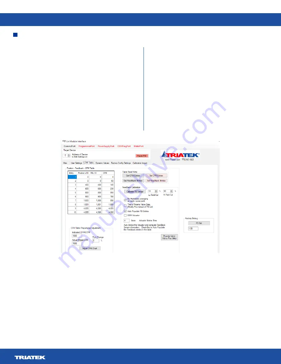
Figure 8. CFM Table Tab
The feedback calibration process will take an A/D reading at
these two positions both from the up-going and down-going
direction and take the average. This is to account for any
hysteresis in the feedback sensor reading.
There is also a checkbox
Do Hysteresis averaging on each curve
point
that enables the average up and down reading on each
of the curves actuator positions for the feedback sensor. This
improves accuracy, but will take longer to execute.
With the feedback sensor properly attached and the actuator
position curve downloaded to the controller, click the
Calibrate
FB Sensor
button.
The tool will automatically position the actuator at the
Hi Field
Cal
and
Lo Field Cal
positions, approaching from both directions
and getting the average A/D reading from which to compute the
gain and offset for the feedback sensor.
It will then position the actuator at each of the position points
in the table and take a corresponding reading from the sensor.
If the
Hysteresis
box is checked, it will take readings of the
position, approaching from both directions and taking the
average. It will convert that into a feedback sensor position and
enter it in the table. When complete, the
Set Feedback Entries
button will become enabled. Click this button to download the
values to the controller.
This procedure is relevant to the Triatek style installation where
the valve is calibrated to the actuator position and cfm value.
With other valve styles, typically in retrofit situations, where the
valve information is not from Triatek, the valve may contain a
feedback position, or feedback voltages and cfm values. The tool
has the provision to open a dialog where feedback voltages and
cfm values can be entered. This is done with the
Phoenix Valve
Volt to Pos
button. Click this to bring up the entry chart.
CFM Table Tab


