
Prestige SOLO 399
Burner Mounting Plate Kit
Instructions:
1. Turn power to the unit “OFF” and allow unit to
cool.
2. Shut off gas supply to the inlet of the unit at the
main manual shutoff valve to the unit.
3. Remove the front panel of the Prestige by
removing the thumb screw on the upper edge of
the unit. Lift the panel up and pull forward to
remove the front panel from the unit.
4. Remove the retaining screw from the control
panel. Open the display panel cover and swing
the control panel out (MCBA).
5. Depress the retaining clips and tilt the control
panel down (TriMax).
6. Remove the air inlet elbow from the venturi
using a twisting motion.
7. Disconnect the gas supply piping inside the
Prestige enclosure at the brass union located
just below the gas valve.
8. Disconnect wiring from gas valve.
9. Disconnect the ignition cable from the igniter
(MCBA), and remove the ground wire at the
igniter.
To ease the removal of the burner assembly,
remove the top jacket access panel.
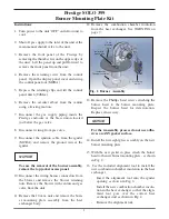
10. Disconnect the wiring harness connectors from
the blower and remove the blower retaining
nuts. Remove the blower with venturi and gas
valve from the unit.
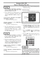
11. Remove the 10 mm nuts and remove the burn-
er mounting plate assembly from the heat
exchanger body.
12. Remove the combustion chamber insulation
from the heat exchanger. See WARNING on
page 7.
13. Remove the Phillips head screws attaching the
burner head to the burner mounting plate.
Inspect the burner head for deterioration.
Replace if necessary.
For the reassembly process do not use adhe-
sives on ANY gasket surface.
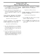
14. Install the new sight glass assembly on the new
burner mounting plate.
15. With the new gasket in place attach the burner
head to the new burner mounting plate , as shown
in Fig. 2.
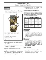
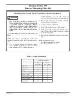
16. Use the included alignment tool to install the
new combustion chamber insulation in the heat
exchanger.
- Insert the alignment tool into the igniter
opening as shown in Fig. 3.
- Install the new combustion chamber insula-
tion in the heat exchanger so that the align-
ment tool goes over the correct heat
exchanger stud as shown in Fig. 4.
- Remove the alignment tool.
NOTICE
NOTICE
2
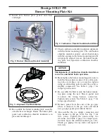
10 mm
Mounting
nuts
Ignitor with
ground wire
Gas Piping
Union
Combustion
Chamber Insulation
Fig. 1: Burner Assembly


