TriangleTube Prestige Trimax 175 Installation Instructions Manual Download Page 7

7

PRESTIGE IGNITION KIT - INSTALLATION INSTRUCTIONS

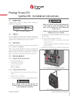
Fig. 12 -  - Prestige Solo & Excellence - PCB Wiring - POSTMOD

Gr

Br

W Bk

V

F00

F01

V

To left side casing 

grounding tabs

Connect to uncon-

nected Molex 

connector in exist-

ing boiler wiring

DO NOT reconnect 

original boiler 

wiring Molex 

connector here

Connec

t her

e

Bk. Black
Br. Brown
R. Red
V. Violet
W. White
Gr.   Green

Summary of Contents for Prestige Trimax 175

Page 1: ...x 20 Flue gas analyzer 1 4 2 Preparation Procedure 1 Turn the boiler off by pressing the on off power switch 2 Allow boiler to cool down 3 Disconnect electrical power at the external electric box Avoi...

Page 2: ...W Bk V Fig 3 Prestige Solo Excellence Ignition Kit Item Description Qty 1 Igniter 1 Screws igniter 2 Gasket igniter 1 Bracket spark generator not illustrated 1 2 Spark generator 1 3 Wiring spark gene...

Page 3: ...r intake 3 from venturi Retain for reinstallation Before disconnecting any wire connections mark and label all connections and location of the connections 2 Open top access panels by removing top acce...

Page 4: ...Required 0 221 5 6mm Table 2 Orifice Sizes 1 5 4 Removing the Burner and Insulation 1 Remove heat exchanger bracket located at the back of the heat exchanger Discard bracket 2 Remove burner plate nut...

Page 5: ...nnection 1 5 9 Checking the Combustion Settings 1 Turn boiler on 2 Allow the appliance to stabilize and insert the gas an alyzer probe in the top vent adapter measuring port 3 Check combustion values...

Page 6: ...s 1 5 10 Return to Service 1 Reinstall the air intake on the venturi 2 Close top access panel as required 3 Check that all wiring connections are secure 4 Check that the gas connection is tight 5 Supp...

Page 7: ...llence PCB Wiring POSTMOD Gr Br W Bk V F00 F01 V To left side casing grounding tabs Connect to uncon nected Molex connector in exist ing boiler wiring DO NOT reconnect original boiler wiring Molex con...

Page 8: ...68 F 20 C 188 F 87 C CH1 Minimum Setpoint 120 F 49 C 60 F 15 C 188 F 87 C Reset Curve Coldest Day 0 F 18 C 30 F 34 C 50 F 10 C Reset Curve Warmest Day 64 F 18 C 60 F 15 C 78 F 25 C CH2 Circuit Enable...

Reviews: