


6
PRESTIGE IGNITION KIT - INSTALLATION INSTRUCTIONS
Fig. 9 - Spark Generator and Bracket (PT 175)
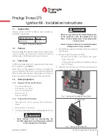
Fig. 10 - Throttle and Offset Locations
NG
LP
H
igh F
ire
CO2
9.5%
11.2%
O2
4.0%
4.0%
CO
< 100 ppm
<100 ppm
Lo
w F
ire
CO2
9.5%
11.2%
O2
4.0%
4.0%
Table 3 - Recommended Combustion Levels
• If the CO2 combustion level during low fire
(1%) differs by more than 0.4% from the
recommended combustion setting (See
Table
3
), remove plastic cover from Offset screw (See
Fig. 10
) and adjust as follows:
• Counter-clockwise adjustment of the offset
screw at Low Fire : O2 increases, CO2 decreases
• Clockwise adjustment of the offset screw at
Low Fire : O2 decreases, CO2 increases.
1.5.10 Return to Service
1. Reinstall the air intake on the venturi.
2. Close top access panel, as required.
3. Check that all wiring connections are secure.
4. Check that the gas connection is tight.
5. Supply power to the boiler through the external elec-
tric box.
6. Open gas supply.
7. Turn boiler on using the boiler On/Off switch.
8. Perform any required configuration change in the Tri-
Max setup according to the initial settings indicated
in
“Default Values and Adjustments” on page 8
.
9. Reinstall the boiler front panel.
10. On the rating plate of the appliance, install the
sticker provided with the kit. This will indicate that
the boiler has been upgraded with the ignition kit,
for future reference.
Fig. 11 - Prestige Solo & Excellence - Rating Plate Correction
PU
Stick here
B
C
A
Offset
Throttle
(Remove
plastic cover
to access
screw)


