background image

Maintenance Procedures

6-Month Maintenance

Check Water and Gas Piping

1.  Remove  the  appliance  front  jacket  panel  and  per-

form a gas leak inspection per steps 1 through 6 of
the Operating Instructions on page 7.  If gas odor
or  leak  is  detected,  immediately  shut  down  the
appliance following procedures on page 7.  Call a
qualified service technician.

2.  Visually  inspect  for  leaks  around  the  internal  appli-

ance  water  connections  and  around  the  heat
exchanger.  Visually inspect the external system pip-
ing, circulators, and system components and fittings.
Immediately  call  a  qualified  service  technician  to
repair any leaks.

Have leaks fixed at once by a qualified service tech-
nician.  Failure to comply could result in severe per-
sonal injury, death or substantial property damage.

Operate Pressure Relief Valve

1.  Before  proceeding,  verify  that  the  relief  valve

outlet  has  been  piped  to  a  safe  place  of  dis-
charge, avoiding any possibility of scalding from
hot water.

To  avoid  water  damage  or  scalding  due  to  valve
operation, a discharge line must be connected to the
relief valve outlet and directed to a safe place of dis-
posal.    This  discharge  line  must  be  installed  by  a
qualified  service  technician  or  heating  /  plumbing
installer  in  accordance  with  the  CHALLENGER
installation manual.  The discharge line must be ter-
minated  so  as  to  eliminate  possibility  of  severe
burns  or  property  damage  should  the  valve  dis-
charge.

WARNING

WARNING

2.  Read  the  temperature  and  pressure  gauge  to

ensure the system is pressurized.  Lift the relief
valve top lever slightly, allowing water to relieve
through the valve and discharge piping.

3.  If water flows freely, release the lever and allow

the  valve  to  seat.    Watch  the  end  of  the  relief
valve  discharge  pipe  to  ensure  that  the  valve
does  not  weep  after  the  line  has  had  time  to
drain.  If the valve weeps, lift the lever again to
attempt  to  clean  the  valve  seat.    If  the  valve
does  not  properly  seat  and  continues  to  weep
afterwards,  contact  a  qualified  service  techni-
cian to inspect the valve and system.

4.  If the water does not flow from the valve when

you  lift  the  lever  completely,  the  valve  or  dis-
charge line may be blocked.  Immediately shut
the appliance down per the instructions on page
7.  Call a qualified service technician to inspect
the valve and system.

6

Summary of Contents for Challenger

Page 1: ...of this or any other appliance WHAT TO DO IF YOU SMELL GAS Do not try to light any appliance Do not touch any electrical switch do not use any phone in your building Immediately call your gas supplier from a neighbor s phone Follow the gas supplier s instructions If you cannot reach your gas supplier call the fire department Installation and service must be performed by a qualified installer servi...

Page 2: ...ation Page 2 Potential Contaminating Products Areas likely to find these Products SECTION II Maintenance Schedule Page 3 Service Technician Owner Maintenance SECTION III Maintenance Procedures Page 4 Periodic Maintenance Monthly Maintenance 6 Month Maintenance SECTION IV Operations Instructions Page 7 SECTION V Appliance Control Display Page 8 Replacement Parts Page 13 ...

Page 3: ...l instructions on installa tion operation or maintenance which are important to equipment but not related to personal injury hazards Indicates recommendations made by Triangle Tube for the installers which will help to ensure optimum operation and longevity of the equipment NOTICE WARNING CAUTION BEST PRACTICE DANGER The following terms are used throughout this manual to bring attention to the pre...

Page 4: ...ce s combustion air inlet See page 2 for details The CHALLENGER is equipped with a low water cut off device The CH central heating system piping must be filled and pressurized to 12 psig 0 8 bar prior to startup The appliance will shut down if the pressure falls below 7 psig 0 5 bar Should overheating occur or the gas supply fail to shut off DO NOT turn OFF or disconnect the elec trical supply to ...

Page 5: ...lue gas spillage or water leakage into the surrounding area Please read the following information If contami nating chemicals will be present near the location of the combustion air inlet the installer should pipe the combustion air inlet to another location per the CHALLENGER installation manual WARNING WARNING Potential Contaminating Products Spray cans containing chloro fluorocarbons Permanent ...

Page 6: ...form Additional items if combustion or performance is poor Clean heat exchanger and flue ways Remove burner assembly and clean burner head using compressed air only Once the maintenance items are completed review the service with the owner Owner Maintenance Periodic Check the area around the appliance Check and remove any blockage from the combus tion air inlet and ventilation openings Check the t...

Page 7: ... combus tion air inlet piping and locate the combustion air intake away from the contaminated areas WARNING WARNING NOTICE 1 Combustible flammable materials Do not store combustible materials gasoline or other flammable vapors or liquids near the appliance Remove immediately if found 2 Air contaminates Products containing chlorine or fluorine if allowed to contaminate the com bustion air will caus...

Page 8: ...ion 2 If you notice flue gas leaking from the opening this indicates a dry condensate drain trap Fill the condensate trap assembly Contact a quali fied service technician to inspect the appliance and condensate line and refill the condensate trap if problem persists regularly WARNING Under some circumstances the CHALLENGER may not produce enough condensate to keep the con densate trap full of liqu...

Page 9: ...nnected to the relief valve outlet and directed to a safe place of dis posal This discharge line must be installed by a qualified service technician or heating plumbing installer in accordance with the CHALLENGER installation manual The discharge line must be ter minated so as to eliminate possibility of severe burns or property damage should the valve dis charge WARNING WARNING 2 Read the tempera...

Page 10: ... Turn Off Gas to Appliance below and call your service technician or gas supplier 11 Replace the front jacket panel Make sure the panel is seat ed firmly in place and all mounting screws are tightened If you do not follow these instructions exactly a fire or explosion may result causing property damage personal injury or loss of life 1 Set the room thermostat to lowest setting 2 Turn OFF all elect...

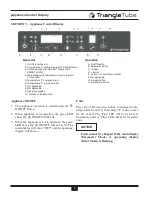
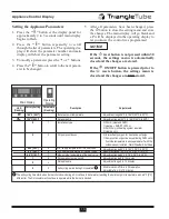
Page 11: ...pplicable G Service button H Reset store button Read Out Operation Appliance ON OFF 1 The appliance operation is started using the ON OFF button 2 When appliance is in operation the green LED above the ON OFF will be lit 3 When the appliance is not in operation the green LED above the ON OFF will not be lit The main display will show OFF and the operating display will show Units Press Up or Down a...

Page 12: ... The LED will be lit for DHW domestic hot water call with optional Triangle Tube SMART I F W H NOTICE when appliance is ON X represents temperature or pressure readings When temperature is displayed it will be followed by ºF or ºC in the main display and the appropriate LED will be lit When pressure is displayed it will be followed by a P in the main display Pres sure can only be read when the ope...

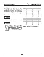
Page 13: ...9Cº 0 Combi Heat and DHW 2 DHW only no heating system required 3 Heating only CH pump continuous 0 0 Intermittent pump on for heat and post purge 1 Pump continously active except during DHW call or if outside temperature is above parameter 7 with the outdoor sensor installed Warm Weather Shut Down 1 Heating SMART I F W H Min supply temperature of the heat curve 86ºF 30Cº Adjustment range 60 F to 1...

Page 14: ... The error code is located on the main display The error must be corrected before the control will reset The appliance freeze protection feature is disabled during a Hard Lockout however the CH circulator will operate During a hard lockout or low water condition the appliance will not re start without serv ice If the heating system is left unattended in cold weather appropriate safeguards or alarm...

Page 15: ...sed Remove air from gas pipe Gas supply pressure too low or failing Gas valve or ignition unit not powered Incorrect ignition gap Check adjustment of gas valve Poor flame signal Condensate drain blocked Check adjustment of gas valve Flame detection fault Replace ignition cable spark plug cap Replace ignition unit at gas valve Replace boiler controller Incorrect fan speed Fan catching on casing Wir...

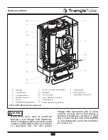
Page 16: ...R Internal Components Replacement parts must be purchased through a local Triangle Tube distributor When ordering part please provide the model number and description and or part number of replacement part Use only genuine Triangle Tube replacement parts to ensure warranty coverage and to avoid damage to appliance and improper operation of appli ance Contact Triangle Tube at 856 228 8881 or www tr...

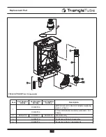
Page 17: ... Number CC85s Part Number CC105s Part Number CC125s Description 1 CCRKIT04 Wall Bracket Assembly Not Shown 2 CCRKIT05 Pipe Connectors Brackets Assembly Not Shown 2A CCFTG01 Connector Pipe CH Not Shown 1 Kit 3 CCRKIT06 CCRKIT07 CCRKIT08 Front Door Assembly ...

Page 18: ...Number CC105s Part Number CC125s Description 1 CCRKIT09 80 125 Concentric Vent Air Adapter Assembly option shown CCRKIT35 3 Vent Air Adapter Assembly standard not shown 2 CCRKIT10 CCRKIT11 CCRKIT12 Vent Assembly 3 CCRKIT13 Condensate Collector Assembly 4 CCRKIT14 Condensate Drain Trap Assembly ...

Page 19: ...Number CC105s Part Number CC125s Description 1 CCRKIT15 Igniter Assembly 2 CCCLB01 Ignition Cable 3 CCRKIT16 Sight Glass Assembly 4 CCRKIT17 CH Sensor Assembly 1 Kit 7 CCRKIT19 LWCO CH Pressure Sensor Assembly 8 CCRKIT20 CCRKIT21 CCRKIT22 CH Supply pipe Assembly 9 CCRKIT23 CH Return Pipe Assembly ...

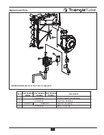
Page 20: ...ER Blower Gas Valve Components Item Part Number CC85s Part Number CC105s Part Number CC125s Description 1 CCRKIT28 Ignition Transformer Assembly 2 CCRKIT29 Gas Valve Assembly 3 CCRKIT30 CCRKIT31 Gas Pipe Assembly 4 CCRKIT32 Blower Assembly ...

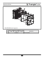
Page 21: ...18 Replacement Parts 1 CHALLENGER Burner Components Item Part Number CC85s Part Number CC105s Part Number CC125s Description 1 CCRKIT33 Burner Assembly ...

Page 22: ...arts 3 4 2 1 CHALLENGER Control Components Item Part Number CC85s Part Number CC105s Part Number CC125s Description 1 CCCON01 Control Display 2 CCCS01 Housing Plastic Control 3 CCRKIT34 Flip Panel 4 CCFUSE01 Fuse 1 Kit ...

Page 23: ...Notes ...
Page 24: ...ure maximum heat exchange Compact and light weight Available in 5 sizes that can accommodate any size pool or spa Exclusive tank in tank design Stainless steel construction Available in 8 sizes and 2 models Limited LIFETIME residential warranty 15 year limited commercial warranty Self cleaning self descaling design For domestic water snow melting radiant floor refrigeration Plates made of stainles...

Reviews: