background image

30

TRI TOOL INC.

92-1783  Orig. 161006

13.   ILLUsTRATeD PARTs BReAkDOWN

MODeL 216B BeVeLMAsTeR, AIR (P/N 01-2246)

1

2

3

4

5

8

9

10

11

12

13

14

15

16

17

18

19

20

21

22

23

24

6 7

Summary of Contents for BEVELMASTER 216B

Page 1: ...92 1783 Orig 161006 Model 216B BEVELMASTER ...

Page 2: ...te service solutions including turnkey project management machining services and mechanized and manual code welding services using experienced and well trained machinists and welders In addition to developing industry leading machining and welding equipment Tri Tool s engineering team provides custom equipment design and manufacturing solutions to suit the most rigorous requirements of our custome...

Page 3: ...ON 7 4 SPECIFICATIONS 8 5 SETUP 10 6 MACHINING OPERATION 17 7 CUTTING SPEEDS 19 8 JAW BLOCKS RAMPS AND SPACERS 20 9 standard tool bits 22 10 maintenance 23 11 troubleshooting 26 12 accessories 28 13 illustrated parts breakdown 30 92 1783 Orig 161006 Model 216B BEVELMASTER ...

Page 4: ...lity is assumed for any incidental or consequential damages Some states do not allow limitations on how long an implied warranty lasts and some states do not allow the exclusion or limitations incidental or consequential damages so the above limitation of exclusion does not apply to all purchasers This warranty gives the purchaser specific legal rights Other rights vary from state to state Tool Bi...

Page 5: ...n this Manual Failure to follow the instructions or follow the safety instructions could result in serious injury or death This manual describes conditions and hazards that are common and anticipated during equipment operation No manual can address all conditions which may occur 2 SAFETY 2 1 safety symbols The manual may contain one or more safety symbols These symbols and the associated text warn...

Page 6: ...he operator must follow the safety precautions in this manual and good engineering practices to reduce the risk of injury Before using the equipment the operator must ensure that all safety messages on the equipment are legible 2 4 work area Keep the work area clean Keep the area well lit Keep items such as electrical cords cables rags rigging straps away from rotating equipment Do not use power c...

Page 7: ... sides of the pipe to move 2 6 Tool care Keep tools in good operating condition Sharp tool bits perform better and are safer than dull tool bits Do not use damaged tools Always check your tools for damage especially if a tool has malfunctioned been dropped or hit check it for damage Before you start operating the equipment do no load tests and feed function checks ...

Page 8: ...se Remove adjusting keys and wrenches before applying power to the equipment Check the tool before turning it on to make sure that all keys and wrenches have been removed Do not force tools Tools and tool bits function better and safer when used at the recommended speeds Do not reach into rotating equipment Do not reach into the rotating head stock to remove chips to make adjustments or to check t...

Page 9: ...reparation for welding These machining operations may be performed either simultaneously or separately Pipe weld preparations that meet all existing conventional codes including the more stringent nuclear codes may be machined using the Model 216B BEVELMASTER The various interchangeable Jaw Blocks Ramps and Spacers will secure the Model 216B BEVELMASTER to pipe and tubing with an inside diameter o...

Page 10: ...or 6 pipe schedules 10 through 160 for 16 pipe and all schedules of 8 through 14 pipe Basic Tube Sizes Up to 1 50 38 1 mm wall tubing with a maximum O D of 16 00 406 4 mm and a minimum I D of 5 18 131 5 mm may be beveled with the standard mandrel Wall Thickness Capacity Wall thickness of all standard pipe schedules 1 500 38 1 mm maximum in the range listed Tubing or pipe with a greater wall thickn...

Page 11: ... MAX ROTATION 34 31 871 4 16 54 420 1 16 19 411 3 14 54 11 54 369 3 239 1 3 00 76 2mm AXIAL TRAVEL 3 JAW BLOCKS 6 THRU 16 PIPE 22 86 580 6 18 44 468 5 MAX ROTATION ON OFF SAFETY LEVER 10 44 265 3 12 38 314 3 14 18 11 54 369 3 293 1 3 00 76 2mm AXIAL TRAVEL 28 96 735 6 3 JAW BLOCKS 6 THRU 16 PIPE LATHE STAND ...

Page 12: ...ill prevent rusting and freezing of the rotor vanes For Hydraulic Motors refer to their Operator s Manual for specifics When the unit is operated in the vertical position cutting head up turn it upside down and remove the chips and or other debris after each cutting operation has been completed Tool life may be severely shortened unless chips and or other debris are removed 5 2 GETTING STARTED 1 S...

Page 13: ...e the adjustment screw to move the tool holder up or down Tighten the told holder lock down screws when the tool holder is in position to prep the pipe Fig 3 9 Insert the tool bit s into the slot s in the tool holder s 10 The cutting edge of the tool bit s must be located on the radial centerline 11 Ensure that none of the tool bits are installed backwards 12 Tighten the tool bit set screws to sec...

Page 14: ...ially to control counterbore diameter Adjust the bevel tool bit radially to control the counterbore depth to the bevel relationship Tool Bit Cutting Edge Tool Bit Set Screws Tool Holder Adjustment Screw Adjustment Screw Adjustment Screw Tool Holder Lock Down Screw Figure 3 Tool Holder Nomenclature ...

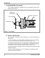
Page 15: ...ew Beveling Tool Block Steel Counterboring Tool Block Aluminuml Facing Tool Block Aluminuml Set Screws Refer to section 9 Standard Tool Bits to select the tool bits for the operation Make sure the Tool Bits s are installed in the correct Tool Block s This reduces Tool Bit wear Refer to Fig 4 ...

Page 16: ...raight Tool Bit may be used for beveling refer to Fig 6 When the 37 5 Facing Tool Bit is used the Tool Bit height is adjustable Refer to Fig 7 for a Tool Block with a Facing Tool Bit Install either the Compound Bevel Tool Bits or J Bevel Tool Bits in this Tool Block Rotation Hex Wrench Tool Bit Tool Block Set Screw 1 Make that the Tool Bit s sit flush against the Slot and then tighten the Locking ...

Page 17: ...ER 92 1783 Orig 161006 Pipe Tool Bit Beveling Model 216B BEVELMASTER Feed Handle Mandrel Stop Tool Bit Bevel Figure 6 Bevel Pipe Tool Bit Facing Model 216B BEVELMASTER Feed Handle Mandrel Stop Tool Bit Facing Figure 7 Facing ...

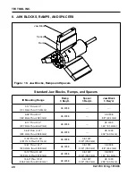
Page 18: ...for burrs and remove them with a file 2 Install the machine into the pipe To avoid cutting the Jaw Blocks with the tool bits during the machining operation the Jaw Blocks on the Mandrel Head must be installed beyond the final end preparation location Refer to Fig 9 3 Tighten the Draw Rod clockwise to force the Jaw Blocks out against the inside diameter of the pipe 4 Verify a minimum clearance of 1...

Page 19: ...pe closer together 4 The machining operation begins when the first tool bit contacts the pipe 5 When the pipe end is not square to the pipe axis the tool bit contacts only a small segment of the pipe during each revolution Pipe Jaw Block Final Prep Location Mandrel Stop Mandrel Draw Nut Ramp Block Feed Handle Tool Holder Deadman Switch Flow Control Valve CAUTION CAUTION Do not operate machine with...

Page 20: ...d allow the head to rotate one to three revolutions to improve the finish of the prep surface 10 Rotate the Feed Handle counterclockwise to separate the Tool Bit s from the pipe 11 Release the trigger to stop the head rotation 12 Rotate the feed handle counterclockwise until the tool bit is 1 8 3 mm minimum from the end of the pipe or tube 13 Loosen the draw nut on the mandrel to release the mandr...

Page 21: ...10 12 6 6 625 168 3mm 10 13 15 Use 200 surface inches per minute 5080 surface millimeters per minute for Stainless steels in general when no coolant is allowed all heavy wall tube and some chrome molybdenum steels Use 250 surface inches per minute 6350 surface millimeters per minute for Mild steels and some thin wall stainless steels when coolants are permitted and applied Use 300 surface inches p...

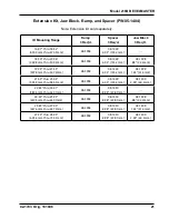
Page 22: ...08 1398 88 22 4mm 8 17 thru 9 72 207 5mm thru 246 9mm 48 3958 08 1399 1 63 41 4mm 9 66 thru 11 21 245 4mm thru 284 8mm 48 3958 08 1400 2 38 60 5mm 11 09 thru 12 64 281 7mm thru 321 1mm 48 3958 08 1397 3 08 78 2mm 12 61 thru 14 17 320 2mm thru 359 8mm 48 3958 08 1397 3 08 78 2mm 08 1398 88 22 4mm 14 10 thru 15 66 358 2mm thru 397 8mm 48 3958 08 1397 3 08 78 2mm 08 1399 1 63 41 4mm 15 60 thru 17 16 ...

Page 23: ...u 21 55 507 8mm thru 547 4mm 48 3958 08 1449 6 03 153 2mm 08 1399 1 63 41 4mm 21 49 thru 23 05 545 9mm thru 585 5mm 48 3958 08 1449 6 03 153 2mm 08 1400 2 38 60 5mm 22 85 thru 24 41 580 5mm thru 620 1mm 48 3958 08 1450 8 98 228 1mm 24 39 thru 25 95 619 5mm thru 659 1mm 48 3958 08 1450 8 98 228 1mm 08 1398 88 22 4mm 25 89 thru 27 45 657 6mm thru 697 2mm 48 3958 08 1450 8 98 228 1mm 08 1399 1 63 41 ...

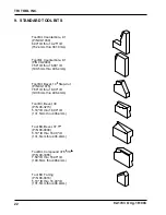
Page 24: ...6 4mm 92 1738 STANDARD TOOL BIT Tool Bit Bevel 10 Step Cut P N 99 1075 7 50 ID thru 16 00 ID 190 5mm thru 406 4mm Tool Bit Bevel 37 5 P N 99 0009 5 18 ID thru 16 00 ID 131 5mm thru 406 4mm Tool Bit Compound 37 5 10 P N 99 3355 7 50 ID thru 16 00 ID 190 5mm thru 406 4mm Tool Bit Bevel 30 P N 99 3273 5 18 ID thru 16 00 ID 131 5mm thru 406 4mm Tool Bit Facing P N 99 0016 5 18 ID thru 16 00 ID 131 5mm...

Page 25: ...a high string utility grease P N 68 0024 10 2 Air MOTOR LUBRICATION No maintenance is usually required on the air motor However the air supply must flow through a filter regulator lubricator FRL unit or separate units before arriving at the air motor The FRL unit must be maintained as required frequency dependent on the basic air supply to keep the water trap drained filter cleaned and the lubrica...

Page 26: ...Exxon Nuto H32 Shell Tellus Oil 32 The bearings in the air or electric motor which are sealed do not require lubrication 10 4 Tightening THE FRONT BUSHING Refer to illustration on next page Tighten the Tapered Split Bushing when the Mandrel Shaft is loose by doing the following 1 Rotate the Feed Handle to extend the Mandrel outward to the limit 2 Remove the tool modules from the headstock to provi...

Page 27: ...25 Model 216B BEVELMASTER 92 1783 Orig 161006 Front Tapered Bushing Flat Head Screw Retaining Plate Feed Housing Gear Headstock Tightening Front Bushing Figure 11 Tightening the Front Bushings ...

Page 28: ...ausing surface hardening conditions Stainless pipe or tubing There is scale or other foreign matter on the pipe or tube which is dulling the tool bit at the start of the cut The tool bit is incorrect for the material being cut Problem Rough Surface Finish The tool bit is dull chipped etc Metal build up on the cutting edge of the tool bit is creating a false cutting edge Cutting fluid is required T...

Page 29: ... installed Problem Air Motor Does Not Start The air power supply is shut off The air motor is damaged and will not run free The air motor needs lubrication Add lubrication and do not run the air motor for a few minutes then try running the motor Tap on the side of the air motor casing lightly with a piece of wood or with a soft rubber mallet just in case the vanes may be sticking Sand or other for...

Page 30: ...5 1219 ID Tracking Kit P N 05 1390 Single Point Flange Facer Kit P N 05 1391 3 Jaw Extension Kit P N 05 1404 Metal Shipping Storage Case P N 86 0386 Air Caddy FRL P N 75 0115 Spare parts and standard tool bits are available from stock 12 ACCESSORIES CAUTION CAUTION An Air Caddy FRL Filter Regulator Lubricator is required to protect the warranty on all TRI TOOL air driven tools ...

Page 31: ...29 Model 216B BEVELMASTER 92 1783 Orig 161006 Page intentionally left blank ...

Page 32: ...30 TRI TOOL INC 92 1783 Orig 161006 13 ILLUSTRATED PARTS BREAKDOWN Model 216B BEVELMASTER AIR P N 01 2246 1 2 3 4 5 8 9 10 11 12 13 14 15 16 17 18 19 20 21 22 23 24 6 7 ...

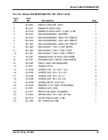
Page 33: ...16B BEVEL 1 9 08 1406 BLOCK ASSY TOOL 216B FACE 1 10 08 1407 BLOCK ASSY TOOL 216B C BORE 1 11 19 1742 HOUSING ASSY DRIVE LOW SPEED 1 12 19 1743 HOUSING ASSY DRIVE HIGH SPEED 1 13 30 0887 PLATE DATA BEVELMASTER 1 14 41 1128 HANDLE PULL 2 15 33 0043 SCREW CAP 1 4 20 X 1 1 4 4 16 33 0055 SCREW CAP 5 16 18 X 7 8 4 17 33 0056 SCREW CAP 5 16 18 X 1 8 18 33 0069 SCREW CAP 3 8 16 X 3 4 3 19 33 0995 SCREW ...

Page 34: ...32 TRI TOOL INC 92 1783 Orig 161006 Model 216B BEVELMASTER Hydraulic P N 01 2247 1 2 3 4 5 8 9 10 11 12 13 14 15 16 17 18 19 20 21 22 23 24 6 7 ...

Page 35: ... TOOL 216B BEVEL 1 9 08 1406 BLOCK ASSY TOOL 216B FACE 1 10 08 1407 BLOCK ASSY TOOL 216B C BORE 1 11 19 1742 HOUSING ASSY DRIVE LOW SPEED 1 12 19 1743 HOUSING ASSY DRIVE HIGH SPEED 1 13 30 0887 PLATE DATA BEVELMASTER 1 14 41 1128 HANDLE PULL 2 15 33 0043 SCREW CAP 1 4 20 X 1 1 4 4 16 33 0055 SCREW CAP 5 16 18 X 7 8 4 17 33 0056 SCREW CAP 5 16 18 X 1 8 18 33 0069 SCREW CAP 3 8 16 X 3 4 3 19 33 0995...

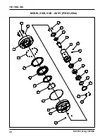
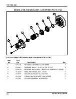
Page 36: ...34 TRI TOOL INC 92 1783 Orig 161006 Model 216B SUB ASSY P N 02 2994 24 21 25 8 18 4 11 3 16 1 13 25 12 17 5 7 22 23 10 20 2 9 6 14 19 15 ...

Page 37: ...9 29 0002 BRG BALL 2 15 16X 3 7 8 X 7 16 1 10 29 0145 BRG BZ 3 7 8 X 4 45 X 1 5 32 1 11 29 0747 BEARING X ROLLER 200ID X 280OD X 30MM 1 12 33 0038 SCREW CAP 1 4 20 X 1 2 6 13 33 0072 SCREW CAP 3 8 16 X 1 1 4 8 14 33 0286 SCREW BUTTON 1 4 20 X 5 8 6 15 33 0298 SCREW BUTTON 3 8 16 X 3 4 1 16 33 1213 SCREW LOW CAP 1 4 20 X 5 8 16 17 33 1418 SCREW FLAT HD 10 24 X 5 16 2 18 33 4231 SCREW LOW HD 5 16 18...

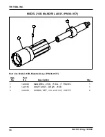
Page 38: ...6 Part List Model 216B Mandrel Assy P N 06 0571 Item No Part No Description Qty Model 216B mandrel ASSY P N 06 0571 1 2 3 1 13 0603 MANDREL 216B 4 DIA 3 TRAVEL 1 2 14 0155 SHAFT ASSY DRAW 216B 1 3 33 0653 SCREW SET 3 8 24 X 3 4 CUP PT 2 ...

Page 39: ... List Model 216B Shaft Assy Draw P N 14 0155 Item No Part No Description Qty Model 216B shaft ASSY draw P N 14 0155 1 3 4 2 1 11 0163 DRAW ROD ASSY 216B 1 2 32 0055 PIN ROLL 1 4 DIA X 1 1 2 1 3 33 4230 SCREW FEED 216B 1 4 35 0152 NUT HEX 1 12 X 55 64 1 ...

Page 40: ...D 216B 1 2 23 0685 ROD DRAW 3 4 16 X 16 375 216B 1 3 24 4416 PLATE BUTT SMALL 216B 1 4 31 0380 KEY RAMP 216B 3 5 32 0118 PIN DOWEL 3 8 DIA X 3 4 4 6 33 0520 SCREW SET 5 16 18 X 1 CUP PT 1 7 33 0965 SCREW SHOULDER 1 2 X 1 3 8 33 2369 SCREW CAP 5 16 18 X 6 1 2 6 9 33 4242 SCREW CAP 10 24 X 1 4 ZINC PLATED 6 10 34 0233 WASHER NYLON 630 O D X 375 I D 6 11 35 0177 NUT JAM 3 4 16 X 27 64 1 12 48 3958 BL...

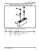
Page 41: ...1006 Part List Model 216B Block Assy Adapter P N 08 1397 Item No Part No Description Qty Model 216B Block ASSY adapter P N 08 1397 1 2 3 1 33 0110 SCREW CAP 1 2 13 X 2 1 4 2 2 34 0382 WASHER NYLON 795 O D X 507 I D 2 3 48 3957 BLOCK ADAPTER 1 ...

Page 42: ...Block Assy Jaw 2 375 P N 08 1400 Item No Part No Description Qty Model 216B Block ASSY jaw 875 P N 08 1398 1 2 3 1 33 0104 SCREW CAP 1 2 13 X 7 8 2 2 34 0382 WASHER NYLON 795 O D X 507 I D 2 3 48 3959 BLOCK JAW 875 1 1 33 0105 SCREW CAP 1 2 13 X 1 2 2 34 0382 WASHER NYLON 795 O D X 507 I D 2 3 48 3960 BLOCK JAW 1 625 1 1 33 0108 SCREW CAP 1 2 13 X 1 3 4 2 2 34 0382 WASHER NYLON 795 O D X 507 I D 2...

Page 43: ...lock ASSY Tool bevel P N 08 1405 1 2 3 4 5 6 7 8 1 14 0160 ROD ASSY ADJUST 216B 1 2 24 4397 PLATE NUT 216B TOOL MODULE 2 3 33 0071 SCREW CAP 3 8 16 X 1 8 4 33 0225 SCREW CAP 5 16 24 X 1 1 4 4 5 33 0286 SCREW BUTTON 1 4 20 X 5 8 2 6 33 0516 SCREW SET 5 16 18 X 1 2 CUP PT 10 7 47 2624 BRACKET TOOL MODULE BEVEL 1 8 49 1907 HOLDER TOOL BEVEL FACE 1 ...

Page 44: ...Y Tool FACE P N 08 1406 1 2 3 4 5 8 6 7 1 14 0160 ROD ASSY ADJUST 216B 1 2 24 4397 PLATE NUT 216B TOOL MODULE 2 3 33 0071 SCREW CAP 3 8 16 X 1 8 4 33 0225 SCREW CAP 5 16 24 X 1 1 4 4 5 33 0286 SCREW BUTTON 1 4 20 X 5 8 2 6 33 0516 SCREW SET 5 16 18 X 1 2 CUP PT 10 7 47 2642 BRACKET TOOL MODULE FACE C BORE 1 8 49 1907 HOLDER TOOL BEVEL FACE 1 ...

Page 45: ...ock ASSY Tool counterbore P N 08 1407 4 8 3 7 6 5 1 2 1 14 0160 ROD ASSY ADJUST 216B 1 2 24 4397 PLATE NUT 216B TOOL MODULE 2 3 33 0071 SCREW CAP 3 8 16 X 1 8 4 33 0225 SCREW CAP 5 16 24 X 1 1 4 4 5 33 0286 SCREW BUTTON 1 4 20 X 5 8 2 6 33 0516 SCREW SET 5 16 18 X 1 2 CUP PT 10 7 47 2642 BRACKET TOOL MODULE FACE C BORE 1 8 49 1908 HOLDER TOOL C BORE 1 ...

Page 46: ...ng ASSY low speed P N 19 1742 5 1 3 6 2 2 4 7 1 19 1737 HOUSING GEARBOX LOW SPEED 1 2 29 0011 BEARING BALL 1 5 16 X 2 1 16 X 7 16 2 3 29 0746 BEARING BALL ANG 12MM I D X 32MM O D X 10MM 1 4 30 3233 RING RETAINING EXT 1 5 16 1 5 33 1213 SCREW LOW CAP 1 4 20 X 5 8 2 6 39 1303 GEAR PINION DRIVER LOW SPEED 1 7 43 1182 COVER GEARBOX LOW SPEED 1 ...

Page 47: ...ousing ASSY high speed P N 19 1743 5 1 3 6 2 2 4 7 1 19 1736 HOUSING GEARBOX HIGH SPEED 1 2 29 0011 BEARING BALL 1 5 16 X 2 1 16 X 7 16 2 3 29 0746 BEARING BALL ANG 12MM I D X 32MM O D X 10MM 1 4 30 3233 RING RETAINING EXT 1 5 16 1 5 33 1213 SCREW LOW CAP 1 4 20 X 5 8 2 6 39 1302 GEAR PINION DRIVER HIGH SPEED 1 7 43 1181 COVER GEARBOX HIGH SPEED 1 ...

Page 48: ...3 Orig 161006 Part List Model 216B Handle Air P N 41 1125 Item No Part No Description Qty Model 216B handle air P N 41 1125 1 2 3 1 24 4389 PLATE FEED 1 2 41 1118 HANDLE STUD 1 2 X 5 13 1 3 42 0017 KNOB SPHERICAL 1 3 8 DIA 1 ...

Page 49: ...ion Qty Model 216B motor assy r a air 3 4 sq P N 57 0354 2 1 7 4 3 5 6 1 33 0071 SCREW CAP 3 8 16 X 1 2 2 47 2683 BRACKET ASSY TORQUE RESTRAINT AIR 1 3 53 0016 VALVE BALL SHUTOFF 1 2 PIPE 1 4 54 0019 NIPPLE 1 2 EPIPE TO 1 2 EPIPE 1 5 54 0126 COUPLING MALE Q D TO 1 2 EPIPE 1 6 54 0201 CAP YELLOW 1 7 57 0159 AIR MOTOR R A 3 4 SQ 1 ...

Page 50: ...6B Bracket Assy Torque Restraint Air P N 47 2683 Item No Part No Description Qty Model 216B BrKt Assy Torque restraint AIR P N 47 2683 2 1 3 1 32 0257 PIN DOWEL 5 16 X 7 8 1 2 33 0073 SCREW CAP 3 8 16 X 1 1 2 1 3 47 2682 BRACKET TORQUE RESTRAINT 216B AIR 1 ...

Page 51: ...49 Model 216B BEVELMASTER 92 1783 Orig 161006 Model 216B motor assy hydraulic P N 56 0159 5 3 1 2 4 6 10 8 9 9 7 10 6 11 ...

Page 52: ...HEAR 1 4 DIA X 1 41 1 3 33 0075 SCREW CAP 3 8 16 X 2 2 4 33 0108 SCREW CAP 1 2 13 X 1 3 4 2 5 47 2627 BRACKET TORQUE RESTRAINT HYD 1 6 54 0002 ADAPTER 7 8 O RING TO 1 2 37D 2 7 54 0333 COUPLER Q D HYD DRIPLESS FEMALE 1 8 54 0334 NIPPLE Q D HYD DRIPLESS MALE 1 9 54 0335 DUST PLUG DRIPLESS 2 10 55 0156 HOSE ASSY HYD 3 4 MP TO 5 8 HOSE 8 2 11 56 0035 MOTOR MOD HYD 1 ...

Page 53: ......

Reviews: