background image

Tri-M Technologies Inc.

Toll Free: 1.800.665.5600

Direct: +1.604.945.9565

Email: [email protected]

Web: www.tri-m.com

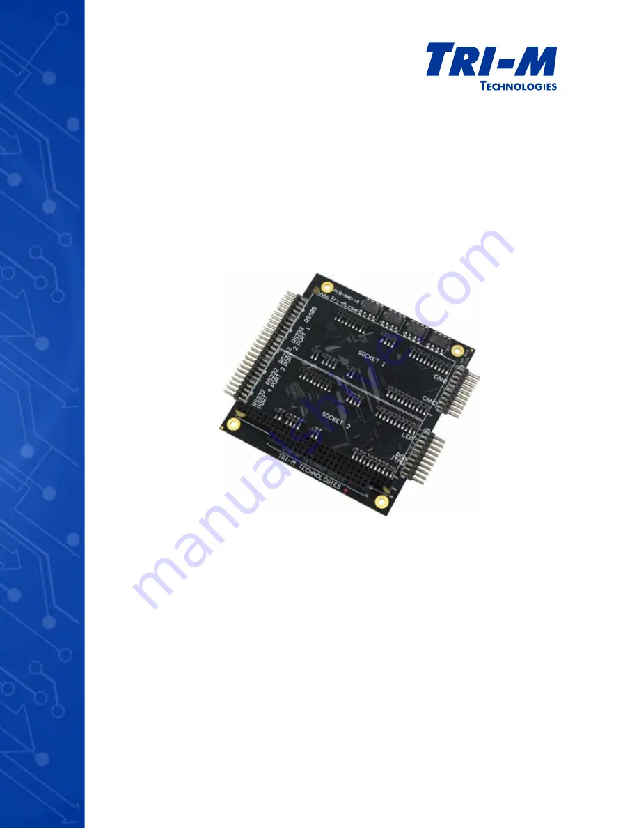
TCB1000 Series

User Guide

CAN Bus, Socket Modems & Serial Communication 

Summary of Contents for TCB1000 Series

Page 1: ...Tri M Technologies Inc Toll Free 1 800 665 5600 Direct 1 604 945 9565 Email info tri m com Web www tri m com TCB1000 Series User Guide CAN Bus Socket Modems Serial Communication ...

Page 2: ...n The user should be familiar with practicing safe techniques while making supply or pin connections User Guide Revision History Revision Date Description A Mar 2012 Added Linux kernel information and ISP pin programming options B Apr 2012 Added CABLESET002 information Trademarks Trademarks registered trademarks and product names are the property of their respective owners and are used herein for ...

Page 3: ...shock even if the board has not been switched on yet Electrostatic Discharge ESD Precautions To avoid electrostatic discharge or transient voltage damage to the board observe the following procedures Before touching the board discharge your body and any tools you use from electricity Ensure that the board or the unit you want to install the board on is de engergized before installing Do not touch ...

Page 4: ...7 Options 7 Specifications 8 Electrical Specifications 8 Mechanical Specifications 8 Environmental Specifications 8 Communication 8 Configuration 8 Certifications 8 Block Diagram 9 Dimensions 10 Connector Locations 11 2 Connectors 12 Connector Specifications 12 PC 104 8 bit Bus CN1 12 PC 104 16 bit Bus CN2 13 RS 232 Ports CN3 CN4 CN5 CN6 14 RS 485 Port CN7 15 JTAG Port CN8 Top 16 USB Port CN8 Bott...

Page 5: ...ART CLOCK DIVIDER 25 SERIAL PORT ENABLE DISABLE 26 DSR 26 RS 485 27 SOCKET RESET 27 CAN BUS MODE 28 CAN BUS 1 28 CAN BUS 2 29 HEART BEAT 29 TEMP 29 ALARM MESSAGE 30 CONFIG 30 A Appendix 31 CABLESET002 31 Serial Cable 31 CAN Bus Cable 32 Utility Cable 32 PGM Config Cable 33 Warranty and Product Information 34 Tri M Technologies Inc Limited Warranty 34 Disclaimer 34 Frequently Asked Questions FAQ 35...

Page 6: ...ctor Pinouts 16 Figure 9 CN9 Connector Pinouts 17 Figure 10 Pin 1 on the Universal Sockets 18 Figure 11 Pins used on the Universal Sockets 19 Figure 12 CN12 and CN13 Connector Pinouts 20 Figure 13 TCB1000 accessed using a USB cable as a Virtual COM Port 21 Figure 14 TCB1000 accessed via a Stack 21 Figure 15 TCB1000 configured as a Mass Storage Device 22 Figure 16 Terminal Command line Application ...

Page 7: ...tion for CAN Bus serial port wired and wireless communication including optional GPS functionality High voltage 2500V port isolation to reduce noise and increase system protection Advanced CAN Bus functionality such as socket network device operation adds flexibility to your embedded system to reduce development time cost and installation setup Jumperless configuration with secure lock ensuring un...

Page 8: ...1x Isolated Port 921Kbp s maximum Can be configured as J1708 Universal Socket Connectivity 2x MultiTech compatible SocketModem 921 Kbp s maximum LED Indicators 5x Isolated LEDs built in limiting resistors USB JTAG 1x USB JTAG Port for easy installation setup Configuration Embedded Design No jumpers required USB JTAG Port Configuration CPLD MCU Programming PC 104 through UART2 PORT4 Configuration P...

Page 9: ...LER ADM3053 ISOLATED Socket 2 Socket 1 TEMP OSCLTR USB RS 232 Isolated RS 232 Isolated RS 232 Isolated RS 232 Isolated RS 485 J1708 Isolated MultiTech Universal 1 MultiTech Universal 2 IRQ Data Addr Data Control IRQ SPI GPIO CS IRQ IRQ CS 14 7456 Mhz Control IRQ Addresses IRQ JTAG I2 C Data Data MCU RS 485 Port RS 232 Port 4 RS 232 Port 2 RS 232 Port 3 RS 232 Port 1 The RS 485 port can be configur...

Page 10: ... Dimensions are in mils 1000 mils 1 inch Pin spacing for the connectors CN3 CN4 CN5 CN6 CN7 CN8 CN9 CN12 and CN13 is 100 mils Figure 2 TCB1000 Dimensions CN7 CN4 CN5 CN3 CN6 CN12 CN13 CN10 CN11 CN9 CN8 A32 C19 D19 B32 2916 475 79 300 677 2157 3150 200 200 200 350 100 500 585 2900 3375 ...

Page 11: ...5 Port 2x5 right angle shroud 0 1 pins Can be configured as J1708 See page 15 CN8 JTAG USB Port 2x5 right angle 0 1 pins 2 Top Bottom See page 16 CN9 5 Isolated LEDs 2x5 right angle shroud 0 1 pins See page 17 CN10 Socket Port 1 Supports Tri M and Universal MultiTech Modules See page 18 CN11 Socket Port 2 CN12 CAN Bus 1 2x5 right angle shroud 0 1 pins See page 20 CN13 CAN Bus 2 1 Introduction CN6 ...

Page 12: ...gnal Pin Signal Pin Signal Pin Signal A1 IOCHCK B1 GND A17 SA14 B17 DACK1 A2 SD7 B2 RESETDRV A18 SA13 B18 DRQ1 A3 SD6 B3 5V A19 SA12 B19 REFRESH A4 SD5 B4 IRQ9 A20 SA11 B20 SYSCLK A5 SD4 B5 5V A21 SA10 B21 IRQ7 A6 SD3 B6 DRQ2 A22 SA9 B22 N A A7 SD2 B7 12V A23 SA8 B23 IRQ5 A8 SD1 B8 0WS A24 SA7 B24 IRQ4 A9 SD0 B9 12V A25 SA6 B25 IRQ3 A10 IOCHRDY B10 GND A26 SA5 B26 DACK2 A11 AEN B11 SMEMW A27 SA4 B...

Page 13: ... CN2 Pin Signal Pin Signal C0 GND D0 GND C1 SBHE D1 MEMCS16 C2 LA23 D2 IOCS16 C3 LA22 D3 IRQ10 C4 LA21 D4 IRQ11 C5 LA20 D5 IRQ12 C6 LA19 D6 IRQ15 C7 LA18 D7 IRQ14 C8 LA17 D8 DACK0 C9 MEMR D9 DRQ0 C10 MEMW D10 DACK5 C11 SD8 D11 DRQ5 C12 SD9 D12 DACK6 C13 SD10 D13 DRQ6 C14 SD11 D14 DACK7 C15 SD12 D15 DRQ7 C16 SD13 D16 5V C17 SD14 D17 MASTER C18 SD15 D18 GND C19 GND D19 GND 2 Connectors Figure 5 CN2 ...

Page 14: ...ise and increase system protection RS 232 Ports 1 to 4 CN3 CN4 CN5 CN6 Top Bottom Pin Signal Pin Signal 1 NC 2 NC 3 RX 4 RTS 5 TX 6 CTS 7 NC 8 NC 9 GNDISO 10 VCC5VISO Note Each port is independently isolated Pin 9 GNDISO and pin 10 VCC5VISO are independently isolated from all other ports 2 Connectors 10 CN6 CN5 CN4 CN3 2 1 9 Figure 6 CN3 to CN6 Connector Pinouts CN7 CN4 CN5 CN3 CN6 CN12 CN13 CN10 ...

Page 15: ...n configuring the RS 485 port see RS 485 on page 27 2 Connectors Figure 7 CN7 Connector Pinouts 1 2 9 10 CN7 CN4 CN5 CN3 CN6 CN12 CN13 CN10 CN11 CN9 CN8 A32 C19 D19 B32 RS 485 Port CN7 Top Bottom Pin Signal Pin Signal 1 J1708 2 J1708 3 RX 4 TX 5 TX 6 RX 7 NC 8 Z120Ω Enable 9 GNDISO 10 VCC5VISO Note The software configuration command RSZ will take precedence when set and RSZ takes precedence on the...

Page 16: ...P to ground puts the USB port in firmware replacement mode Leaving the ISP pin unconnected lets you edit the settings using the config txt file The config txt files will be overwritten if the firmware bin is entirely rewritten and the disk containing the config txt resides in the upper 4KB of the firmware bin JTAG Port CN8 Pin Signal 1 VCC3V3 3 TMS 5 TCK 7 TDI 9 TDO Note The JTAG port is for facto...

Page 17: ... CN6 CN12 CN13 CN10 CN11 CN9 CN8 A32 C19 D19 B32 5 5 1 1 LED Port CN9 LED Top Bottom Description Pin Signal Pin Signal LED1 1 LED 1 LED LED1 shows the status activity of a network module inserted in socket 1 It is powered by the RS 232 port 1 isolated power LED2 2 LED 2 LED LED2 shows the status activity of a network module inserted in socket 2 It is powered by the RS 232 port 2 isolated power LED...

Page 18: ...nication Tri M developed its own GPS module and provides a variety of socket modules including Ethernet CDMA GSM GPRS Wi Fi and Bluetooth For specific product information please visit http www tri m com products multitech Figure 10 shows the location of pin 1 on the universal sockets 2 Connectors Figure 10 Pin 1 on the Universal Sockets CN12 CN13 CN10 CN11 CN9 CN8 1 1 Pin 1 CN10 CN11 ...

Page 19: ... 38 37 36 35 34 33 RESET LED_RX LED_TX RST RX TX RI DSR CTS DCD DTR GND LED_ACT LED_LNK LED_SPD VCC5V AGND Universal Socket Universal Sockets Pin Signal 24 RESET 30 LED_RX 32 LED_TX 33 RST 34 RX 35 TX 36 RI 37 DSR 38 CTS 39 DCD 40 DTR 41 GND 57 LED_ACT 58 LED_LNK 60 LED_SPD 61 VCC5V 63 AGND Figure 11 Pins used on the Universal Sockets Figure 11 and the table provide a list of the pins used on the ...

Page 20: ...the board and is enabled when pin 6 LOAD ON and pin 7 LOAD T are connected and unpowered nodes do not disturb the bus resulting in secure and reliable network signaling provide up to 2500V channel isolation maximum speeds up to 1 Mb s and slope control to reduce EMI have thermal shutdown protection 2 Connectors CAN Bus BUS CN12 CN13 Top Bottom Pin Signal Pin Signal 1 N C 2 GND ISO 3 CAN Bus 4 CAN ...

Page 21: ...ort can CAN C1 0x00000600 10 C2 0x00000680 10 ser SER U1PI 0x0300 5 U1P2 0x0308 5 U1P3 0x0310 5 U1P4 0x0318 5 U2P1 0x0200 5 U2P2 0x0208 5 U2P3 0x0210 5 U2P4 0x0218 5 u1p 256 U1P 0x0100 ser SER U1P1 0x0100 5 U1P2 0x0108 5 U1P3 0x0110 5 U1P4 0x0118 5 U2P1 0x0200 5 U2P2 0x0208 5 U2P3 0x0210 5 U2P4 0x0218 5 File Edit View Terminal Go Help CAUTION Locked configuration settings can only be unlocked by a...

Page 22: ...ake up to 25 seconds to identify and mount the device NXP LPC1342 microcontroller in programming mode ISP on to access the firmware bin There is no delay in configuration mode to access the config txt file 3 Configuration Drag and Drop File Transfer Configured as USB Mass Storage Device USB Cable TCB1000 Powered or Unpowered CAUTION Although the device is recognized as a mass storage device space ...

Page 23: ...ansmit and receive lines See page 27 SOCKET RESET Manually resets Socket 1 or Socket 2 See page 27 CAN BUS MODE Configures CAN Bus for BASIC or PeliCAN PORTIO or MEMIO Assigns the same IRQ for both CAN Bus controllers See page 28 CAN BUS 1 Configures the IRQ addresses and slew rate for CAN Bus controller 1 See page 28 CAN BUS 2 Configures the IRQ addresses and slew rate for CAN Bus controller 2 Se...

Page 24: ...IRQ used by UART1 Port 2 RS 232 Port 2 U1I3 Displays the IRQ used by UART1 Port 3 RS 232 Port 3 U1I4 Displays the IRQ used by UART1 Port 4 RS 232 Port 4 UART 1 These commands allow you to configure UART1 which controls the RS 232 ports 1 to 4 Write Command Value Default Description U1P The ADDRESS RANGE is from 0x100 to 0x3E0 by steps of 0x20 For instance 0x100 0x120 0x3C0 0x3E0 0x100 Assign a bas...

Page 25: ...ed by UART2 Port 2 Socket 1 U2I3 Displays the IRQ used by UART2 Port 3 Socket 2 U2I4 Displays the IRQ used by UART1 Port 4 CPU UART 2 These commands allow you to configure UART2 which controls the RS 485 port Socket Modem 1 Socket Modem 2 and CPU UART CLOCK DIVIDER These commands allows you to assign a divider value for the UART Clock f 14 7456MHz Note Write Commands take effect when you enter the...

Page 26: ... port SERIAL PORT ENABLE DISABLE These commands allow you to enable or disable the four RS 232 ports and the RS 485 port You can also assign Serial Port 8 to be connected to the CPU or GPIO pins on the Universal Socket 2 Note that disabling the ports will also affect the power of the LEDs Read Command Description RS1 Displays the Enable Disable status of Serial Port 1 RS 232 Port 1 RS2 Displays th...

Page 27: ...ns the RXDE connection RS 485 Receive enable to ALWAYS or when not transmitting TXDE CTS R or C R Assigns the connection of Serial Port 5 RS 485 to RTS or CONTROLLED by the CPU DLY The time range is from 0 to 4095 and stated in 1 10 of a ms 100 Assigns the controlled delay assigned to CTS of Serial Port 5 RS 485 in 1 10 ms RS 485 These commands allow you to configure the RS 485 transmit and receiv...

Page 28: ... the IRQ addresses and the slew rate for CAN Bus controller 1 3 Configuration CAN BUS MODE These commands allow you to configure the CAN Bus for BASIC or PeliCAN PORTIO or MEMIO and assign the same IRQ for both CAN Bus controllers Write Command Value Default Description CI IRQ 5 6 7 10 11 12 15 10 Assigns an IRQ for both CAN Bus controllers CD P or M P Assigns the CAN Bus address decoding to PORTI...

Page 29: ...rns the current on board temperature reading in Kelvin TAL Returns the temperature low limit in Kelvin TAH Returns the temperature high limit in Kelvin Read Command Description CAN Bus Displays the address and IRQ used by both CAN Bus controllers C2 Displays the address and IRQ used by CAN Bus controller 2 C2P Displays the address used by the CAN Bus controller 2 C2I Displays IRQ used by the CAN B...

Page 30: ...ion profile Config txt and lock any changes Write Command Value Default Description UPD Applies the changes live on the running hardware STD Saves the changes to flash RLD Reload the configuration profile from flash LCK L or U U Locks any change from Serial Port 8 and can only be unlocked from the USB virtual COM port it can be pre locked in config txt Read Command Description CFG Displays the ent...

Page 31: ...3408m Figure 17 Serial Cable SRXDB2 SRTSB2X STXDB2 SCTSB2X SRXDB1 SRTSB1X STXDB1 SCTSB1X SRXDB4 SRTSB4X STXDB4 SCTSB4X SRXDB3 SRTSB3X STXDB3 SCTSB3X RXA RXB TXY TXZ 485EN GNDISO1 GNDISO2 GNDISO3 GNDISO4 GNDISO5 1 2 3 4 5 6 7 8 9 10 11 12 13 14 15 16 17 18 19 20 21 22 23 24 25 26 27 28 29 30 31 32 33 34 35 36 37 38 39 40 41 42 43 44 45 46 47 48 49 50 1 6 2 7 3 8 4 9 5 1 6 2 7 3 8 4 9 5 1 6 2 7 3 8 ...

Page 32: ... CAN Bus Cable Figure 19 Utility Cable 1 2 3 4 5 6 7 8 9 10 LED1ISO LED2ISO LED3ISO LED4ISO LED5ISO LED OUT LED1R LED2R LED3R LED4R LED5R 1 2 3 4 5 6 7 8 9 10 CONFIG PGM USBDM USBDP VUSB 1 2 3 4 5 6 7 8 9 10 11 12 13 14 15 16 17 18 19 20 TDI TDO TCK TMS ISPX GND VCC3V3 CABLESET002C LEDS PGM WIR 100 20 IDC Length 12 inches 0 3048m CAN1L CAN1H CAN2EOL CAN2L CAN1EOL CAN2H VISO6 VISO7 GNDISO6 GNDISO6 ...

Page 33: ...56 feet 2 meters Figure 20 PGM Config Cable USBDM USBDP VUSB 1 2 3 4 5 6 7 8 9 10 11 12 13 14 15 16 17 18 GND 1 2 3 4 USBDM USBDP VUSB GND CABLESET002D USB 19 20 1 2 Note The jumper between pin 18 and pin 20 allows the use of the cable in configuration debug mode Jumper ON Set the cable to programming mode Jumper OFF Set the cable to configuration debug mode ...

Page 34: ...liable for consequential damages arising out of its obligations under this warranty or the failure or incorrect use of any of its products This warranty is in lieu of all warranties either express or implied including without limitation any implied warranty of merchantability or fitness for any particular purpose and of any other obligation on the part of Tri M Disclaimer No part of this document ...

Page 35: ...RT and the IOaddr of the other three ports automatically follow the first one For instance by default UART1 is set to 0x100 meaning that RS 232 port 1 0x100 RS 232 port 2 0x108 RS 232 port 3 0x110 and RS 232 port 4 0x118 UART2 is set to 0x200 meaning that RS 485 0x200 Socket 1 0x208 Socket 2 0x210 onboard uC 0x218 Each port is 8 addresses apart because of their 8 internal registers This is why the...

Reviews: