


15
English
NOTE:
This diagram serves the purpose of illustrating the possible
analog phone / PBX / PSTN integration / applications of the Gateway.
However, disconnect cadence provided by your phone company for
your PSTN line and disconnect cadence provided by your PBX may
require additional matching with the gateway. This will require the
assistance of your PBX supplier and /or Systems Integrator. Please also
see User's Guide for additional information.
Scenario description: Two gateways connected by a switch
There are two gateways connected by a switch. They are generically labeled
“Gateway” but could be any combination of either the TVP-224HR (connected
to switch by WAN port) or TVP-224HR (Connected by LAN port). Theoretically,
GW A is in Taiwan (Local Area Code have 2 digits) and GW B is in the US
(Local Area Codes have 3 digits).
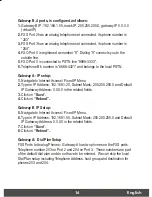
Gateway A, 4 ports, is configured as follows:
1.
Gateway A IP: 192.168.1.20, mask IP: 255.255.255.0, gateway IP 0.0.0.0
(virtual IP)
2.
FXS Port 2 has a telephone set connected, its phone number is “203”
3.
FXS Port 3 has a telephone set connected, its phone number is “204”
4.
FXO Port 0 is connected to PBX. There are two telephone sets connected to
the PBX. Their extension numbers are “800” and “801”.
5.
FXO Port 0 is registered as number “9” and it is connected to PBX
6.
PBX has an external line to PSTN. Dialing “9” connects you PBX, where “9”
is dialed to connect to PSTN.
7.
The PSTN number to reach the PBX is “8888-2222”.
8.
Telephone A's number is “7777-1234” and belongs to the local PSTN


