background image

(800) 275-8558   www.irrigationremotes.com

19

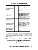
Trouble Shooting Chart 

My Transmitter does 
not beep. 

Check the battery. Using a 
voltmeter or a battery tester, test 
the battery voltage. Replace the 
battery if the voltage is below 
6.8 volts. 

My Transmitter is 
beeping  rapidly. 

Rapid beeps after a transmiision 
is an indication the the battery 
voltage is low. Replace the 
battery with a new high quality 9 
VDC Alkaline battery. 

My Sidekick system is 
not getting any range 

See antenna installation tips for 
proper antenna installation. 

My Sidekick is turning 
off after 20 minutes. 

The Receiver has a default 20 
minute shut off. When a valve is 
activated it remains on for 20 
minutes and shuts off 

My Receiver is not 
getting any power. 

If receiver power light is not on 
check to see that the remote 
interface cable is installed 
properly and the controller has 
power.

For Technical Support call 800-275-8558 Monday through Friday 
7AM - 4PM PST. All goods returned to TRC Irrigation Remotes 
must be accompanied with a RMA. Please use our toll free # to 
obtain a RMA. 

Products returned without an RMA will be 

charged a $150 flat rate, regardless of 

problem.

Summary of Contents for Sidekick FM

Page 1: ......

Page 2: ...nsmitter to transmit up to 5 miles while using only one 9V alkaline battery For best results and to maximize the features and functions of any Sidekick FM system carefully read this manual and keep it...

Page 3: ...re limited in duration to three years following the date of purchase These exclusions or limitations apply only in those states where permitted by law Models and Description Several differing products...

Page 4: ...e not all Rain Bird controllers are remote port ready The Sidekick FM for Hunter PN 01016 is a controller specific receiver designed for Hunter ICC and Pro C controllers The Sidekick FM for Irritrol P...

Page 5: ...the Receiver turning ON or OFF a selected valve as well as the Pump Start Master Valve Station of the receiver automatically When not in use the transmitter reverts to a standby mode which is designe...

Page 6: ...es that the transmission has been completed TransmitterOperatingInstructions Valve On Valve Off To turn a valve On press the desired valve station number then press the On key Pressing Off will turn t...

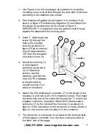
Page 7: ...rminal strip or directly to the valve wires at the controller and bypasses the controller s functions by directly activating the valves Installation Instructions The housing can be mounted to the righ...

Page 8: ...he threaded end of the screw 5 4 Mount the housing 1 to the irrigation controller using two 6 32 x Machine screws two flat washers and two hex nuts NOTE Hardware is not provided to mount housing 1 to...

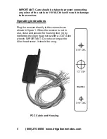
Page 9: ...lt in damage to the receiver Operating instructions Plug the receiver directly in the connector as shown in figure 1 When the receiver is not in use close and secure the housing door 4 by tightening t...

Page 10: ...the Sidekick receiver on more then one controller simply install another PCC RB cable in the other controller Permanent Controller Cable PCC RB Installation 1 Follow PCC installation instructions 1 5...

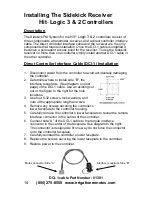
Page 11: ...sconnect power from the controller to avoid accidentally damaging the controller 2 Determine where to install side B the interface receptacle See diagram on next page of the DCI 1 cable Use an existin...

Page 12: ...ck FM Receiver Connect the interface plug to the interface receptacle on the controller Twist the plug clockwise until the plug stops Do not over tight the plug See diagram below Disconnecting the Sid...

Page 13: ...er from the controller to avoid accidentally damaging the controller 2 Determine where to install side B the interface receptacle See diagram on next page of the DCI 1 cable Use an existing cut out or...

Page 14: ...ck FM Receiver Connect the interface plug to the interface receptacle on the controller Twist the plug clockwise until the plug stops Do not over tight the plug See diagram below Disconnecting the Sid...

Page 15: ...er from the controller to avoid accidentally damaging the controller 2 Determine where to install side B the interface receptacle See diagram on next page of the DCI 1 cable Use an existing cut out or...

Page 16: ...ck FM Receiver Connect the interface plug to the interface receptacle on the controller Twist the plug clockwise until the plug stops Do not over tight the plug See diagram below Disconnecting the Sid...

Page 17: ...DCI 1 H Installation 1 Open the front panel door of the controller housing 2 Disconnect power from the controller to avoid accidentally damaging the controller 3 Determine where to install side B the...

Page 18: ...diagram below Disconnecting the Sidekick FM Receiver Twist the circular plug in a counterclockwise motion and remove the plug from the receptacle The Blue wire is connected to the terminal marked REM...

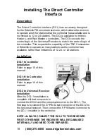
Page 19: ...C Commander or Sidekick to operate as many stations as the controller has available rather than limitations of 12 24 or 32 stations Installation DCI 1 to controller Installation Refer to page 10 of th...

Page 20: ...ntenna installation tips for proper antenna installation My Sidekick is turning off after 20 minutes The Receiver has a default 20 minute shut off When a valve is activated it remains on for 20 minute...

Page 21: ...is noise x Mount all antennas outdoors Our Wireless Switch System both FM transmitter and receiver communicates in the RF radio frequency spectrum at 27 MHz This frequency has great characteristics fo...

Page 22: ......

Reviews: