18 Installation
(for qualified installers only)
Travis Industries
4121102
100-01301
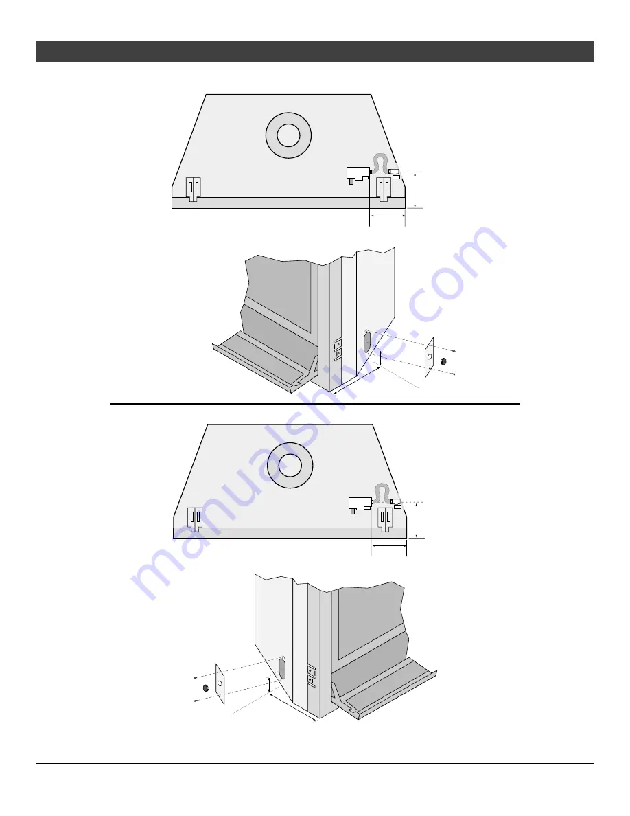
Gas Line Location
8-1/2"216mm
14-3/4"375mm
8-1/2" (216mm)
3" (77mm)
7" (178mm)
Page 1: ...ediately call gas supplier from a neighbor s phone Follow the gas supplier s instructions If you cannot reach your gas supplier call the fire department Installation and service must be performed by a...
Page 2: ...partment clean See installation and operating instructions accompanying appliance This appliance must be properly connected to a venting system in accordance with the manufacturer s installation instr...
Page 3: ...26 Rear Vent Configuration with Horizontal Termination with vertical rise 27 Rear Vent Configuration with Vertical Termination 28 Top Vent Configuration with Horizontal Termination 29 Top Vent Config...
Page 4: ...ect fuel will void the warranty and safety listing and may cause an extreme safety hazard Direct questions about the type of fuel used to your dealer Contact your local building officials to obtain a...
Page 5: ...young children and others may be susceptible to accidental contact burns A physical barrier is recommended if there are at risk individuals in the house To restrict access to a fireplace or stove inst...
Page 6: ...mum BTU Input Per Hour 31 000 31 000 Heating capacity will vary with floor plan insulation and outside temperature Efficiency rating is a product thermal efficiency rating determined under continuous...
Page 7: ...etails Secure the fireplace to the framing Install the vent gas line and electrical hook up Install the drywall Install the hearth if applicable Install the facing if applicable Install the mantel if...
Page 8: ...uilding at a minimum height of eight 8 feet above grade directly in line with the exhaust vent terminal for the horizontally vented gas fueled heating appliance or equipment The sign shall read in pri...
Page 9: ...re the vent configuration is correct prior to installation You may wish to configure the diffuser when changing the vent configuration Converting the Fireplace to Top Vent Configuration Remove and dis...
Page 10: ...plate with the screws removed earlier Attach the cover plate with the screws removed earlier NOTE flatten the four legs before insaling the cover plate Rotate the flue assembly so the flue points upw...
Page 11: ...non combustible surface not on linoleum or carpet This heater may be placed in a bedroom Please be aware of the large amount of heat this appliance produces when determining a location Clearances When...
Page 12: ...e the vent to combustibles Included Firestop required Part 93006094 Center of Rear Vent 30 3 4 781mm 38 965mm 41 1 4 1048mm 38 1 2 978mm 20 508mm HINT place the fireplace so the center line is at leas...
Page 13: ...ng Dimensions Top Vent Configuration Route the electrical line to a position to the left rear of the fireplace 41 1 4 1048mm 38 1 2 978mm 20 508mm The on off switch thermostat wire if used should be r...
Page 14: ...ger tab out 90 F 32 2 C Use a screwdriver if necessary Fireplace Drywall Framing Nailing Bracket TOP VIEW 1 2 13mm Drywall 5 8 16mm Drywall There are four nailing brackets on the front of the fireplac...
Page 15: ...raming dimensions shown in the illustration below NOTE all clearances still apply 7 1 2 91mm Approximate varies due to vent installation 48 Min 1219mm Minimum 1 2 13mm Clearance NOTE Most installation...
Page 16: ...vis Industries 4121102 100 01301 Corner Installations Top Vent Configuration A typical 45 installation uses the framing dimensions shown in the illustration below NOTE all clearances still apply 15 1...
Page 17: ...y pressure testing of that system at test pressures in excess of 1 2 psig 3 5 kPA For pressures under 1 2 psig kPA isolate the gas supply piping by closing the manual shutoff valve Leak test all gas l...
Page 18: ...18 Installation for qualified installers only Travis Industries 4121102 100 01301 Gas Line Location 8 1 2 216mm 14 3 4 375mm 8 1 2 216mm 14 3 4 375mm 8 1 2 216mm 3 77mm 7 178mm 3 77mm...
Page 19: ...er is shut off prior to working on any electrical lines The appliance when installed must be electrically grounded in accordance with local codes or in the absence of local codes with the National Ele...
Page 20: ...ior to disconnection when servicing controls Wiring errors can cause improper and dangerous operation Note When using a GreenSmart remote use the receiver for on off operation do not use a wall switch...
Page 21: ...ed 1 25mm clearance is met Vent Clearances The vent must maintain the required clearance to combustible materials to prevent a fire Do not fill air spaces with insulation Before 48 1219mm Rise After 4...
Page 22: ...r details Always use the high wind cap or high wind sconce cap part 58DVA HSCH or 46DVA HSCH Installation instructions for Simpson Dura Vent may be found at www duravent com Vent Installation Slide th...
Page 23: ...gurations detail the correct vent restrictor positions Exhaust Restrictor Adjustment If the diffuser is required to be in position 2 you may wish to adjust the diffuser while the exhaust restrictor is...
Page 24: ...ntake restrictor is located behind the accent light on the back wall of the firebox To adjust the restrictor follow the steps below Slide the restrictor down to the second position and tighten the scr...
Page 25: ...s flattened See the directions below to change the diffuser to position 2 Back Wall of Firebox Firebox Roof Remove the exhaust restrictor 1 4 6mm Nutdriver Remove the diffuser 1 4 6mm Nutdriver Secure...
Page 26: ...45 Elbow Termination See the charts below to determine maximum vent 3 feet 0 915m 0 feet 0 feet 4 max 1 22m Exhaust Restrictor 1 stock Intake Restrictor 1 stock Diffuser Position 1 stock Vent with No...
Page 27: ...feet 6 m 20 feet 6 m 5 feet 1 5 m 10 feet 3 m 5 feet 1 5 m 10 feet 3 m 0 feet 15 feet 4 5 m 20 max 6 m 10 feet 3 m 15 feet 4 5 m 15 feet 4 5 m 20 max 6 m 10 feet 3 m 15 feet 4 5 m 22 max 6 7 m 22 max...
Page 28: ...eet 6m 20 feet 6m 5 feet 1 5m 10 feet 3m 5 feet 1 5m 10 feet 3m 0 feet 15 feet 4 5m 20 6m max 10 feet 3m 15 feet 4 5m 15 feet 4 5m 20 6m max 10 feet 3m 15 feet 4 5m 40 12m max Exhaust Restrictor 4 Int...
Page 29: ...et 0 feet 5 feet 1 5m 0 feet 20 feet 6m 20 feet 6m 5 feet 1 5m 10 feet 3m 5 feet 1 5m 10 feet 3m 0 feet 15 feet 4 5m 20 6m max 10 feet 3m 15 feet 4 5m 15 feet 4 5m 20 6m max 10 feet 3m 15 feet 4 5m 21...
Page 30: ...tor 4 Intake Restrictor 2 Diffuser Position 2 This is considered a horizontal elbow it does not matter whether it turns right or left It may be a 90 or 45 elbow This is considered a vertical elbow Hor...
Page 31: ...of the gas supplier G Minimum 48 1219mm clearance from any adjacent building H Minimum 84 2134mm clearance above any grade when adjacent to public walkways or driveways NOTE may not be used over a wal...
Page 32: ...ng the fireplace must be raised so the base of the unit is above the carpet surface or flooring material Floor Mounted Fireplaces Raised Fireplaces A hearth is not required when the fireplace is raise...
Page 33: ...Tile or other non combustible facing may be placed on the front of the fireplace see Facing Overview on page 34 for further details Drywall Installation Drywall Installation Drywall may be installed...
Page 34: ...above the base of the fireplace The fireplace may be raised to accommodate thicker hearth materials Optional Faceplates Sizing Chart Name Height Width Notes FPX Artisan Classic Fr Ctry 35 3 4 908mm 4...
Page 35: ...r Raised Fireplaces Facing is installed 1 25mm maximum above the base of the fireplace Facing is installed to this edge of the fireplace FRONT VIEW Tile Line Tile Line Hearth Line Tile Line 34 1 4 870...
Page 36: ...Note how the facing extends 1 25mm above the base of the fireplace 1 25mm Fireplace Support Floor Drywall Tile or other facing under 1 25mm thick Face Floor Max 1 25mm Hearth note how it extends unde...
Page 37: ...Drywall Fireplace Drywall Framing Nailing Bracket Masonry TOP VIEW Protruding Masonry Fireplace Drywall or cement board etc Framing NOTE The nailing brackets are not used for this type of installatio...
Page 38: ...0688 The template helps locate and support the masonry as it being installed Masonry Line Hearth Line Drywall Floor Mounted Fireplaces or Raised Hearths Build the hearth 1 25mm maximum above the base...
Page 39: ...e masonry extends 1 25mm above the base of the fireplace 1 25mm Fireplace Support Floor Floor Mounted Fireplace with Hearth SIDE OF FIREPLACE Drywall Masonry or other non combustible over 1 25mm thick...
Page 40: ...the following requirements must be met Non combustible mantel and facing must extend from the top of the appliance to the top surface of the mantel A non combustible header must be used metal stud 36...
Page 41: ...make sure all vent clearances are met NOTE FOR 2 x 4 51mm X 102mm EXTERIOR WALLS When installed with a 2x4 51mm X 102mm exterior wall the termination may not fit flush against the exterior wall You ma...
Page 42: ...ull requirements 4 102mm Section NOTE FOR 2 x 4 51mm X 102mm EXTERIOR WALLS When installed with a 2x4 51mm X 102mm exterior wall the termination may not fit flush against the exterior wall You may wis...
Page 43: ...l the four AA batteries included in the owner s pack into the battery holder see the illustration below The AA batteries act as a power backup in case the household AC power goes out Install the 9v ba...
Page 44: ...e instructions refer to the Owner s Manual part 100 01302 ACID WASH WARNING Before installing the faceplate make sure any masonry that has been treated with acid wash has been properly neutralized thi...
Page 45: ...Open the six latches holding the glass frame in place start with the bottom three follow the directions shown to the right a Lift the glass frame up and pull it forward to remove b Re Attaching the G...
Page 46: ...1 4 turn when it is disengaged Follow the directions below to re install the latch if it becomes loose Top of Firebox Hold the latch at an angle and insert it into the slot on the glass frame anchor...
Page 47: ...1 Log Set Installation Log Set Overview When installed the ten 10 logs should appear as shown below The directions on the following pages detail installation of this log set Left Twig Front Ember Chun...
Page 48: ...k log has two pockets that insert over two tabs on the back burner see photos below Place the log in place and push it back The log straddles the burner and does not cover any burner holes Right Log T...
Page 49: ...t Log The front left log has a channel that fits over the grate When in place the knob on the front of the log fits over the grate as well Left Log The left log has a channel on the bottom Place this...
Page 50: ...e center twig is shown below It has a pin on the bottom side When in place the fork on the front straddles the grate and the pin rests on the rear burner make sure it is not over any burner holes Fron...
Page 51: ...g as shown below The front left log has a groove that will point the twig upwards and to the right Center Left Twig The left center twig is flat on the bottom and has a fork at one end Place the twig...
Page 52: ...hole on the back and a fork on the front Position the log so this fits over the pin on the back log Make sure the fork on the front of the log fits over the grate as shown below Right Twig The right t...
Page 53: ...ool is placed on top of the burner to enhance the glow from the burner The rock wool works best when it is applied in a very thin porous layer The best method for applying the rock wool is to brush it...
Page 54: ...the burners following the directions below Lift the rear burner slide it to the right and lift it from the firebox The burner has a bracket that inserts over two pins behind the burner When replacing...
Page 55: ...udes 15 16 23 8mm indicating full insertion use wrench to secure manifold when re attaching orifice d Look here for the orifice identification Apply thread sealant to the LP orifices prior to installa...
Page 56: ...erify the hood is tight The clip may also be compressed while in place forcing the clip into the slots on the pilot assembly 5 Replace the firebox components Install the logs and embers Replace the gl...
Page 57: ...tand Remove the rear air deflector two screws hold it in place Remove the exhaust restrictor 4 screws hold it in place Remove the screw holding the accent light assemblies in place Re position the ass...
Page 58: ...ds to engage the upper slot You will need to lift the grill slightly to get it over the bushing Once in place the grill is held in place by gravity Lower Grill Installation Hold the grill at an angle...
Page 59: ...remote Remote Control Pilot Warnings Installing batteries in the battery holder or connecting the appliance to power may automatically initiate the CPI pilot mode resulting in a lit pilot flame Do no...
Page 60: ...round Accessory Power Green Orange Yellow Green White Blue IPI CPI Switch 120 VAC Power In Black Red Yellow Flame Detect Black Black Black White Green Base Integrated Fireplace Control IFC 3 15A FUSE...
Page 61: ...anual On Off Accent Light s 2 5 Amp Fuse Optional Blower s 2 5 Amp Fuse Appliance Ground Accessory Power Appliance Ground Green Orange Yellow Green White Blue IPI CPI JUMPER WIRE Blue Pink 120 VAC Pow...
Page 62: ...qualified installers only Travis Industries 4121102 100 01301 Installation 1 Remove the concealment cover from the heater and set aside 2 Remove the On Off Comfort Control Battery Plate from the cont...
Page 63: ...ment for qualified installers only 63 Travis Industries 4121102 100 01301 3 Remove the control panel and place face down in front of the heater keep the screws 4 Disconnect input power 5 Disconnect th...
Page 64: ...alified installers only Travis Industries 4121102 100 01301 6 Pull the base IFC forward to access the wiring it is held in place with Velcro 7 Disconnect the comfort control wires and battery backup w...
Page 65: ...ove and place aside the base IFC it may be kept for spare parts 10 Remove and place aside the On Off Comfort Control Battery Plate with harness the batteries and assembly may be kept for spare parts 1...
Page 66: ...sheet included with it make sure to follow all of the directions Place the stepper motor on the gas control valve see below MAKE SURE IT IS CORRECTLY ORIENTED Secure using the screws included with the...
Page 67: ...ed in location see e below Wiring the Blower to the GSR2 IFC Bypassing the Rheostat and Snap Disc Disconnect the blower power input see a below Connect the blower wiring harness to the fuse output see...
Page 68: ...r the IFC is placed in location see a below Wiring the Blower to the GSR2 IFC Bypassing the Rheostat Disconnect the accent light power input see a below Disconnect the two wires leading to the rheosta...
Page 69: ...y 69 Travis Industries 4121102 100 01301 15 Attach the following Power 3 wires make sure orientation is correct Pilot connections Make sure silicone tubing is pushed down Comfort Control connection Ma...
Page 70: ...ach one of the jumper wires to the two wires Discard the IPI CP switch 17 Remove the IPI CPI switch and place aside may be kept for spare parts 18 Connect the accent light wires to the GSR2 IFC NOTE I...
Page 71: ...2 Re connect the ground wire 23 Use the two included cable ties to make sure all wiring is secure and does not contact any hot or moving parts 24 Attach the control panel 25 Attach the battery box to...
Page 72: ...or Termination 41 Installation Options 6 Installation Overview 7 Log Set Installation 47 LP Conversion Instructions 54 Mantel Requirements 40 Optional Wall Switch or Thermostat Installation 20 Rear Ve...