


SISTF10xx-111-LR(T) Industrial Media Converter
Transition Networks
24-Hour Technical Support: 1-800-260-1312 International: 00-1-952-941-7600
19
Connecting copper cables
Copper cable
installation
To connect the copper cable to the Media Converter and other equipment, do the following:
Step
Action
1.
Locate or build 10Base-T or 100Base-TX copper cables with male, RJ-45
connectors installed at both ends.
2.
Connect the RJ-45 connector at one end of the cable to the RJ-45 port on
the media converter. See Figure 16 below.
3.
Connect the RJ-45 connector at the other end of the cable to the RJ-45
port on the other device (switch, workstation, PLC, etc.).
4.
Check the copper port LED on the Media Converter to verify the connection—
LNK/ACT LED should be lit.
Figure 16: Copper Cable Installation
Copper cable
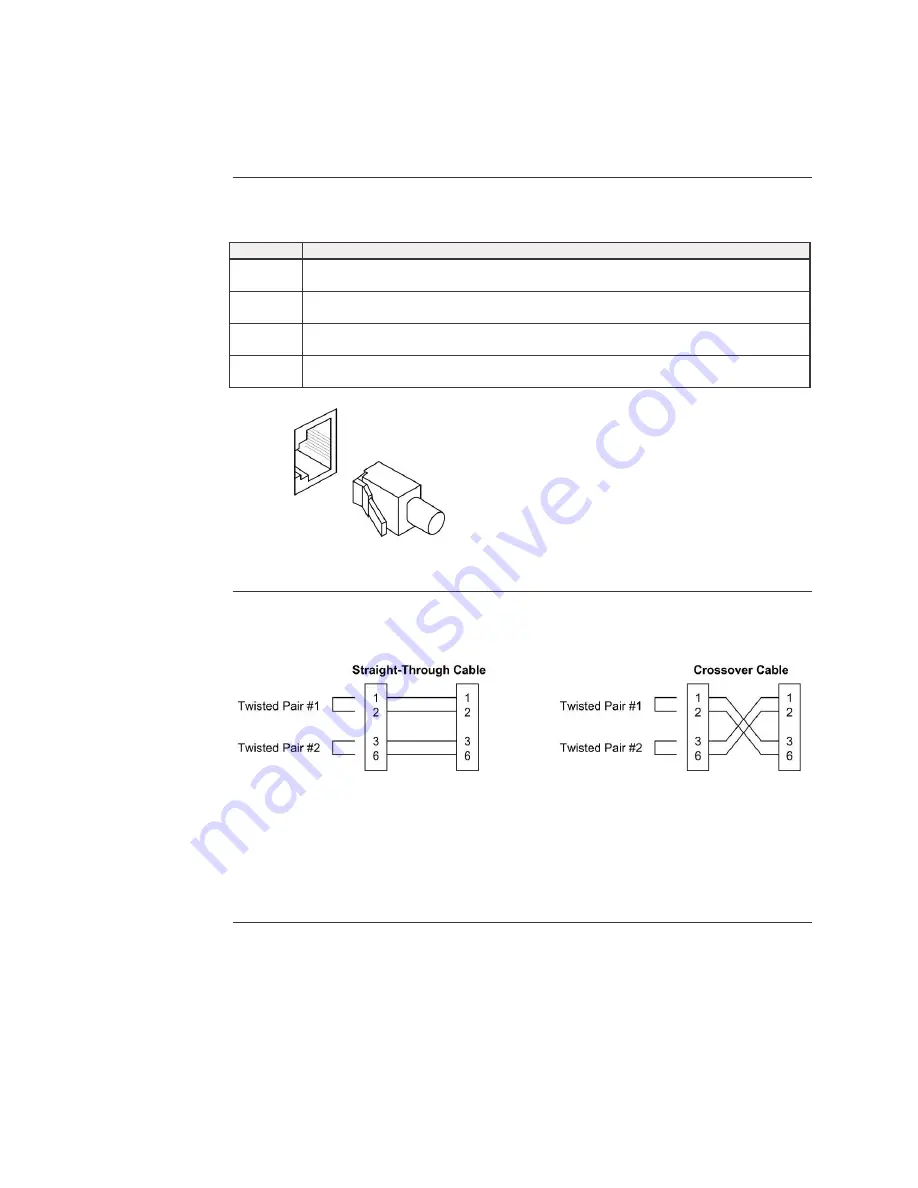
configuration
Either a straight-through or cross-over cable may be used. See Figure 17.
Figure 17: Straight-Through and Crossover Cables
Note
:
The AutoCross
TM
feature determines the characteristics of the cable connection and
automatically configures the unit to link up, regardless of the cable configuration,
allowing either straight-through (MDI) or crossover (MDI-X) cables to be used.
(Requires no operator intervention.). See Advanced Features section for more
information.
Summary of Contents for SISTF10xx-111-LR
Page 2: ......


