


6
CGETF10xx-1xx
24-hour Technical Support: 1-800-260-1312 International: 00-1-952-941-7600
Installation
-- Continued
Install the slide-in-module
IMPORTANT: Slots in the PointSystem™ chassis without a slide-in-module
installed MUST have a protective plate covering the empty slot for Class A
compliance.
To install the CGETF10xx-1xx media converter slide-in-module:
1.
Locate an empty slot on the
PointSystem™
chassis.
2.
Carefully slide the slide-in-module into the slot, aligning it with the slot
guides.
3.
Ensure that the slide-in-module is firmly seated inside the chassis.
4.
Push in and rotate the panel fastener screw shown below clockwise to secure
the module to the chassis front.
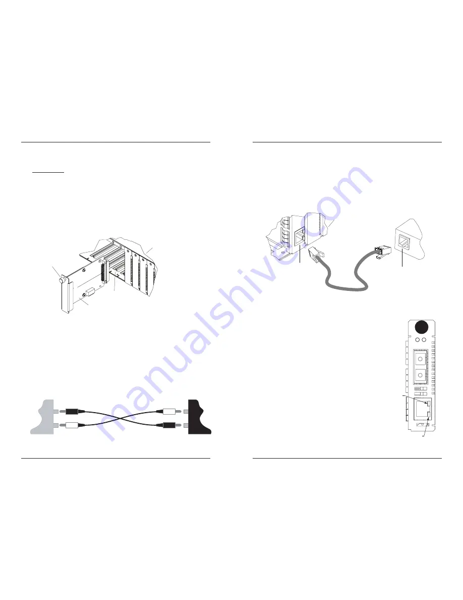
Install the fiber cable
1.
Locate a 1000Base-SX/LX compliant fiber cable with male, two-stranded TX
to RX connectors installed at both ends.
2.
Connect the fiber cable to the CGETF10xx-1xx media converter as described:
•
Connect the male TX cable connector to the female TX port.
•
Connect the male RX cable connector to the female RX port.
3.
Connect the fiber cables to the other device
(another media converter, hub,
etc.)
as described:
•
Connect the male TX cable connector to the female RX port.
•
Connect the male RX cable connector to the female TX port.
Me
d
ia Conve
rt
e
r
Poin
t
S
y
st
em Cha
ss
i
s
Panel Fa
st
ene
r
S
lo
t
RX
TX
TX
RX
Device
Device
[email protected] -- Click the “Transition Now” link for a live Web chat.
7
Installation -- Continued
Install the copper cable
1.
Locate a 1000Base-T compliant copper cables with male, RJ-45 connectors
installed at both ends.
2.
Connect the RJ-45 connector at one end of the cable to the RJ-45 port on the
CGETF10xx-1xx media converter.
3.
Connect the RJ-45 connector at the other end of the cable to the RJ-45 port on
the other device
(switch, workstation, etc.).
RJ-45 Po
rt
Me
d
ia Conve
rt
e
r
RJ-45 Po
rt
On o
t
he
r
d
evice
(
w
o
r
k
s
tatio
n
,
sw
itch, etc.)
Poin
t
S
y
st
em Cha
ss
i
s
Operation
Status LEDs
Use the status LEDs to monitor the CGETF10xx-1xx
media converter operation in the network.
PWR
(Power)
ON =
Connected to external
AC power.
LKF
(Fiber link)
ON = Fiber
Connection
RXC
(Copper receive)
Flashing = Receiving data
on the copper
link.
ON =
Copper Link
connection
Duplex
ON =
Full
LKF PWR
TX
RX
1000Base-X
1000Base-T
Duplex LED
RXC LED


