


4
CGETF10xx-1xx
24-hour Technical Support: 1-800-260-1312 International: 00-1-952-941-7600
Installation
CAUTION: Wear a grounding device and observe electrostatic discharge precautions
when setting the jumper, the 6-position switch, and installing the CGETF10xx-10x
media converter into the
PointSystem™
chassis. Failure to observe this caution could
result in damage to the media converter.
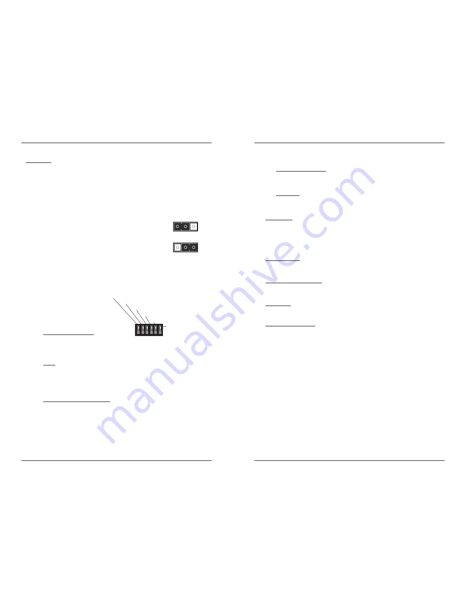
Set the 2-position jumper
•
The jumper is located on the media converter circuit board, connector J5.
•
Use a small needle-nosed pliers or similar device to set the jumper.
•
Refer to the illustration on the right for hardware/software jumper positioning.
Hardware
The media converter’s mode of operation is
determined by the 6-position switch
settings. Default is the Hardware position.
Software
The media converter’s mode of operation is
determined by the most recently saved on-
board microprocessor settings.
Set the 6-position switch
•
The 6-position switch is located on the side of the media converter.
•
Use a small flat-blade screwdriver to set the DIP switches.
•
All switches are shown in the
default position, UP.
Note:
Switch positions S2 and S3
function together to configure
the media converter for Pause
conditions.
S1 Remote-Fault Detection
up
Disabled
down
Enable
S2 & S3 work in combination
Pause
10 sw position 2 up and 3 down:
Symmetric
01 sw position 2 down and 3 up:
Asymmetric
11 sw positions 2 and 3 up: Pause is OFF
(default position)
00 sw positions 2 and 3 down:
Symmetric and Asymmetric
S4 Transparent Link Pass-Through
up
Enable Link Pass-Through
down
Disable Link Pass-Through
H
S
o
ft
wa
r
e Mo
d
e
S
H
Ha
rd
wa
r
e Mo
d
e
S
2. Pause
(symmetric)
3. Pause
(asymmetric)
4. Transparent Link Pass-Through
5. Auto-Negotiation
1. Remote Fiber Fault Detect
6. Loop Back
[email protected] -- Click the “Transition Now” link for a live Web chat.
5
Installation
-- Continued
Set the 6-position switch -- continued
S5 Fiber Auto-Negotiation
up
Disable Auto-Negotiation for the fiber link (
default setting)
down
Enable Auto-Negotiation for the fiber link
S6 Loop Back
up
Disable RX/TX signal loop back
(default setting)
down
Enable RX/TX signal loop back
Install Mode
During installation, set DIP switch 4 DOWN; leave all other switches in the UP
position
(default)
. This disables Transparent Link Pass-Through and Auto-
Negotiation, allowing individual copper and fiber links to be established
(both
copper port LEDs will turn ON with each device-to-device connection)
independent
of having a complete end-to-end connection.
Operation Mode
After installation is complete
(all copper and fiber ports connected and linked),
set
all switches to the UP position
(default)
.
Remote Fiber Fault Detect
Remote fiber fault detect (RFD) monitors the status of the fiber link. Enable RFD in
the remote converter only.
CAUTION: If RFD is enabled in the device at each end of the link, a link pass-
through event will put the converters into an unrecoverable state
(unable to
establish a link)
.
Fiber Auto-Negotiation
Fiber Auto-Negotiation allows the fiber interface to detect and then advertise the
supported features of the remote device—active only when a fiber cable is
connected to a device with a negotiating port. The process is as follows:
1.
The fiber interface detects the supported features of the remote partner.
2.
These abilities are passed to the twisted-pair interface and advertised.
3.
Once the twisted-pair interface has a link at the highest common capability, it
passes the result to the fiber interface.
4.
The fiber interfaces then start advertising these capabilities. At this point, the
link between the fiber and the negotiating port is complete.
If the CGETF10xx-1xx is connected via fiber to another CGETF10xx-1xx, both
media converters must have the Fiber Auto-Negotiation setting disabled
(switch 5
UP)
.
Note:
Transparent Link Pass-Through
(switch position 4 enabled)
cannot be
turned OFF (
disabled)
when Fiber Auto-Negotiation is ON
(enabled).


