background image


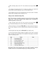
B.2 Recognized Host Commands 

 
“P”

 - This command is sent to the indicator to print the indicator display. The indicator will 

not respond if the system is in motion, positive overload or negative overload. 
 

“Z”

  –  This  command  is  sent  to  the  indicator  to  zero  the  system.  The  indicator  will  not 

respond if the system is in motion, positive overload or negative overload.                         

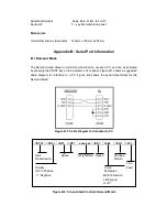
Appendix C: Displayed Error Codes 


Code 

Mode 

Meaning / Possible Solution 

□□□□□□


Normal Operating 
Mode 

Gross Overload. A weight greater than the rated 
capacity  has  been  applied  to  the  system. 
Remove  the  weight  from  the  platter  or  try 
recalibrating the system. Otherwise, check for a 
bad  load  cell  connection  or  possible  load  cell 
damage due to overloading. 

ERR0 

Span Calibration 
Mode (F17) 

Keyed-in  weight  value  is  larger  than  full-scale 
capacity.  Use  a  smaller  test  weight  or  check 
keyed-in value. 

ERR1 

Span Calibration 
Mode (F17) 

Keyed-in  weight  value  is  less  than  1%  of 
full-scale  capacity.  Use  a  larger  test  weight  or 
check keyed-in value. 

ERR2 

Span Calibration 
Mode (F17) 

There is not enough load cell signal to produce 
the  internal  counts  necessary  to  properly 
calibrate  the  system.  First  check  all  load 
connections.  Use  F16  mode  to  view  internal 
counts. 

ERR3 

All Modes 

Non-volatile  memory  read  error.  One  or  more 
setup parameters have been lost. 
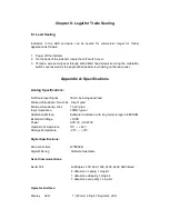


Warranty: 

 
1.  Warranty Period: Twelve (12) months for data of shipment from manufacturer. 
2.  Over the warranty period, the maintenance must be charged. According the product’s 

fault, charge for parts, maintenance and calibration. 

3.  Non-warranty: 

a. Not correct installing, using and storing. 

      b. Not connecting the power correctly. 
      c. Natural disasters and animal damage. 
Immersing the indicator into water, it belongs to non-warranty. 


Summary of Contents for TI-1500B

Page 1: ...TI 1500B Force Gauge Digital Indicator Setup Operation Manual V A2...

Page 2: ...Descriptions 7 Chapter 6 Calibration 7 6 1 Calibration Overview 7 6 2 Zero Calibration F16 8 6 3 Span Calibration F17 8 6 4 View Calibration Values F18 9 6 5 Key in Zero Calibration Value F19 9 6 6 Ke...

Page 3: ...e the manual in a safe and convenient place so it will be available if you have questions concerning the operation of the scale If you are an installer the indicator s installation and wiring instruct...

Page 4: ...e into LOADCELL Port on the rear panel of the indicator Show in figure 2 2 TI 1500B Rear Panel Pin No Pin Name 1 8 Excitation 3 10 Excitation 5 12 Signal 7 14 Signal Figure 2 2 Pin assignments for the...

Page 5: ...ta channel Not need calibrate again In every channel the system has two menus The Setup Menu F Menu which configures the indicator to your force gauge s platform and the User Menu A Menu which configu...

Page 6: ...ss the PEAK SET key To exit without saving press the UNITS key to return to the current F heading 5 Repeat steps 1 through 4 until the Setup Menu is programmed Figure 3 1 Setup Menu Key Assignments 3...

Page 7: ...HANNEL key or PRINT key to move through the selection field 4 To save a new selection press the PEAK SET key To exit without saving press the UNITS key to return to the current A heading 5 Repeat step...

Page 8: ...tion is detected by comparing the present display update with the previous one Maximum value varies depending on local regulations 1d 3d 5d 10d F6 Digital Filter Averages weight readings to produce hi...

Page 9: ...a checkmark Name Code Description Code Value A1 Baud Rate Selects the baud rate for data transmission through the serial port 300 600 1200 2400 4800 9600 A2 Data Bits and Parity Selects the number of...

Page 10: ...tarily then revert back up to F16 At this time proceed to the F17 span calibration to complete indicator calibration 6 3 Span Calibration F17 1 While in the Setup mode scroll to F17 then scroll down o...

Page 11: ...F18 Note The values displayed in this procedure are valid only after a successful calibration has been performed using F16 and F17 1 While in the Setup mode scroll to F18 then scroll down once using t...

Page 12: ...or will prompt you to enter the information in the follow table 2 If the value shown is correct press PEAK SET key to save the value then move to the next value Otherwise use the four directional keys...

Page 13: ...he display detail of the LED LED Annunciator Meaning ZERO This light is active when ever the displayed weight is within zero range PEAK Keeping the peak value When the weight is less than 2 of full ca...

Page 14: ...eeping operation 7 3 3 Keeping Peak Value 1 Press the PEAK key to enter keeping peak value mode The item s weight is from 2 to 100 of full capacity the indicator can record the maximum value in real t...

Page 15: ...Full Scale input Signal 30mV including dead load Minimum Sensitivity Non H 44 0 4 V grad Minimum Sensitivity H 44 1 0 V grad Input Impedance 30M typical Calibration Method Software Calibration with l...

Page 16: ...activated by pressing the PRINT key on the indicator s front panel Figure B 1 shows a suggested cable diagram for interface to a PC Figure B 2 shows the serial data format for the Demand Mode Figure B...

Page 17: ...lue is larger than full scale capacity Use a smaller test weight or check keyed in value ERR1 Span Calibration Mode F17 Keyed in weight value is less than 1 of full scale capacity Use a larger test we...

Page 18: ...75 Deerfield Parkway Buffalo Grove IL 60089 U S A www transcell com Asia Pacific headquarters Tel 886 2 8919 1012 Fax 886 2 8919 1011 E mail info apac transcell com Add 7F No 129 Ln 235 Baoqiao Rd Xin...

Reviews: