Additional Symbols Peak, Zero, N, kN, lbf, mV/V
Keyboard 5 – key flat membrane panel
Mechanical:
Overall Dimensions (Standard) 310mm x 100mm x 205mm
Appendix B: Serial Port Information
B.1 Demand Mode
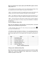
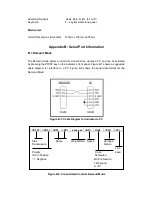
The Demand mode allows control from a host device, usually a PC, and can be activated
by pressing the PRINT key on the indicator’s front panel. Figure B-1 shows a suggested
cable diagram for interface to a PC. Figure B-2 shows the serial data format for the
Demand Mode.
Figure B-1: Cable Diagram for Indicator to PC
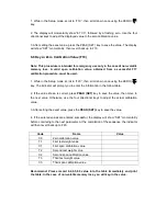
Figure B-2: Consolidated Controls Demand Mode
<STX> <POL> <SP>
<SP>
xxxxx.xx <SP>
Units
<CR> <LF>
Start Space Weight Data Space Carriage
Transmission Return
Line
Polarity Units: Feed
<SP>=Positive N=Newton
“-“= Negative kN=Kilo Newton
LBf=pound
mV/V

