User Manual
TRB4000TL/TRB5000TL/TRB6000TL/TRB8000TL/TRB9000TL/
TRB010KTL
Page 1: ...User Manual TRB4000TL TRB5000TL TRB6000TL TRB8000TL TRB9000TL TRB010KTL...
Page 2: ...trical system design 8 2 3 The illustration of derating and limit the input power 8 3 Operation mode illustration of the inverter 9 3 1 Wait mode 9 3 2 Check mode 9 3 3 Normal mode 9 3 4 Fault mode 10...
Page 3: ...nication 29 6 2 1 RS 232 Communication for Three inverter type 29 6 2 2 RS 485 422 Communication 30 6 2 3 WiFi GPRS Ethernet Communication 30 6 2 4 USB Communication 31 6 3 Monitoring 31 7 Maintenance...
Page 4: ...agiarize partially copy or fully copy it including software etc and no reproduction or distribution of it in any form or by any means All rights reserved Trannergy reserves the right of final interpre...
Page 5: ...ng with electrical equipment 1 3 Applied Designations Warning Caution Note Throughout the manual important information is shown at different levels depending on the character of the information as sho...
Page 6: ...r user and environment only the original spare parts available from your supplier should be used Functional safety parameters Unauthorized changes of functional safety parameters may cause injury or a...
Page 7: ...you while working Make sure that danger areas are clearly marked 1 6 System Sizing When dimensioning a photovoltaic system it must be ensured that the open circuit voltage of the PV string never exce...
Page 8: ...part at the bottom of inverter so take care of the AC output terminals do not make it stand on the ground or other materials while moving or lifting the inverters otherwise will make terminal damaged...
Page 9: ...g and install methods 2 3 The illustration of derating and limit the input power To avoid inverter to be damaged by over temperature or over current Not output power when the temperature of power devi...
Page 10: ...1 State Machine of Inverter working mode 3 1 Wait mode When the input power by solar panel is not enough to let the power module work it is at waiting mode The inverter will wait until the input volta...
Page 11: ...t very serious fault will be cleared after 5s automatically and retry to run If the serious fault generated it will stay in the fault mode until the technical staff to solve the problem 3 5 Flash mode...
Page 12: ...antee of the TRB series inverters during five years after your purchase if the installation site does not meet the instructions described in this manual it is out of warranty The warranty is limited t...
Page 13: ...ll It need repositioning and drilling holes if the hole with much error Step2 Put the expansion pipe showing in Figure 4 3 into the hole vertically use hammer to tap the pipe into the wall completely...
Page 14: ...AC breaker in order that inverter can be safely disconnected under load when installation maintenance Connection Procedure Step1 Switch off the AC breaker secure against being switched back on inadver...
Page 15: ...the following pictures N L 1 2 Figure 4 9 Attention Please ensure the corresponding relationship between polarities the core cable and the hole of the terminal is correct Step6 Screw these components...
Page 16: ...ction at first There are two MPPT trackers A B route provided by the TRB4000TL 5000TL 6000TL 8000TL 9000TL 010KTL and each MPPT tracker provides a pair of DC input interface Attention Connectors must...
Page 17: ...rs are visible in the contact barrel observation hole See below figures Figure 4 14 Crimp contact barrel by using the hex crimping die See below figures Figure 4 15 Amphenol specified crimping tool ca...
Page 18: ...eated correctly See below figures Figure 4 17 Wrest the cap by using the torque of 2 6 2 9NM Figure 4 18 Step2 Mate and separate Helios H4 connector After wrest the cap tightly align the 2 half connec...
Page 19: ...le connected to the two string correctly and it s polarity c The unused terminals are covered Turn on the inverter Step1 Close the DC and AC circuit breaker Step2 If the solar panels provide enough en...
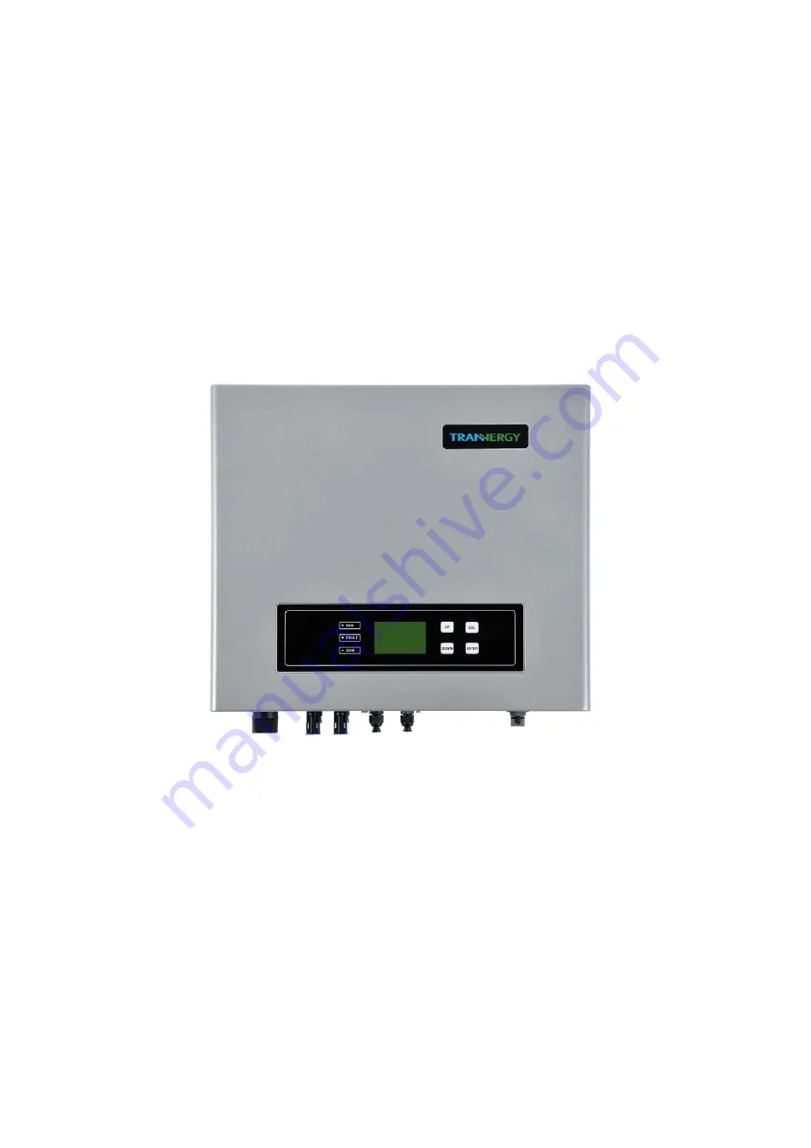
Page 20: ...erface It is showing as the follow Figure 5 1 Figure 5 1 Control and Display Panel Object Description A Working normally Green LED B Fault Red LED C Communication Yellow LED D EXIT Function key E Down...
Page 21: ...V 50Hz and input voltage generated by PV modules is above 200V the green LED lights up Normally this LED begins to light up in the morning when the sunshine intensity is enough and goes out when it ge...
Page 22: ...PV Over Voltage PV input voltage surpasses the tolerable maximum value Fan Lock Fan malfunction AC Voltage Out of Range The measured AC voltage is out of tolerable range Isolation Fault Isolation resi...
Page 23: ...r E today E total At the bottom of LCD display time and date will be shown Figure 5 2 Main Interface 1 When press enter button it will go into main menu telling inverter state energy yield as well as...
Page 24: ...AC Parameter DC Parameter Frequency Energy yield E Week E Month E Year Settings Language and Time Safety Parameters Power Management Clear Data Ethernet Settings Log Error Information Device Informat...
Page 25: ...pressing the up and down keys After finishing setting year please press the down key and move to Month press the enter key to confirm setting set month also by pressing the up and down keys Press the...
Page 26: ...arameter or increase or decrease the parameters These parameters contain Safety Vpv Start T start Vac Min Vac Max Fac Min Fac Max and so on Notes This operation step requires password default value 10...
Page 27: ...you will find a pull down menu Choose Power Management menu and press enter to get into Power Management state In this menu press OK to set power limit and factor type if choosing Default data set de...
Page 28: ...ter key and you will find main menu Move the cursor to Device information by pressing the up or down key and then press the enter key you will find the information of Device Model SN HMI SW CU SW etc...
Page 29: ...pecific fault information will show in window on the LCD showing when the fault happened and the error information At the same time the red LED lights up and the green LED goes out The following figur...
Page 30: ...We offer below 4 type communications 6 2 1 RS 232 Communication for Three inverter type RS 232 is one communication interface It transmits the data between PC and one TRI series inverter Figure 6 1 F...
Page 31: ...485 422 USB Figure 6 2 RS 485 422 Communication Diagram PIN1 TXD _RS 485 422 PIN2 TXD _RS 485 422 PIN3 RXD _RS 485 422 PIN4 GND PIN5 PIN6 RXD _RS 485 422 PIN7 7V DC PIN8 Notes The wires connection seq...
Page 32: ...2 interface is shown below Figure 6 3 The software PVCS in the PC can handle real time monitoring of max 32 inverters at the same time RS485 422 USB To RS485 422 USB RS485 422 RS485 422 Figure 6 3 Mon...
Page 33: ...g detergent to clean them 7 2 Notes of maintain or service When there are faults occurrences the inverter can disconnect from grid automatically and send out fault or warning information The simple fa...
Page 34: ...1 1 1 1 1 1 1 1 1 MPPT number 2 2 2 2 2 2 OUTPUT Operating voltage 220Vac 380 Vac or 230 Vac 400 Vac Number of grid phases 3 3 3 3 3 3 Voltage Range 180 270 Vac 310 Vac 470 Vac Frequency range 50 Hz 6...
Page 35: ...by the customer In addition the type label on the unit must be fully legible If these requirements are not fulfilled we reserve the right to deny warranty services Warranty claims are excluded for dir...
Page 36: ...zzanine Floor 19 19 21 Crawford Street London W1H 1PJ Email service trannergy com Hotline 0845 056 4118 Trannergy Benelux Service Center Address Loosterwegnoord 2J 2161AP Lisse The Netherlands Email s...
Page 37: ...specifications Utility Loss 1 Grid is not connected 2 Check grid connection cables 3 Check grid us ability 4 If grid is ok and the problem exists still maybe the fuse in the inverter is open please c...
Page 38: ...e best services as we can Appendix B Abbreviation AC Alternating Current DC Direct Current DLU Data Logger Unit DSP Digital Signal Processing EEPROM Electrically Erasable Programmable Read Only Memory...
Page 39: ...P N 540 00033 02 Ver 00...