background image

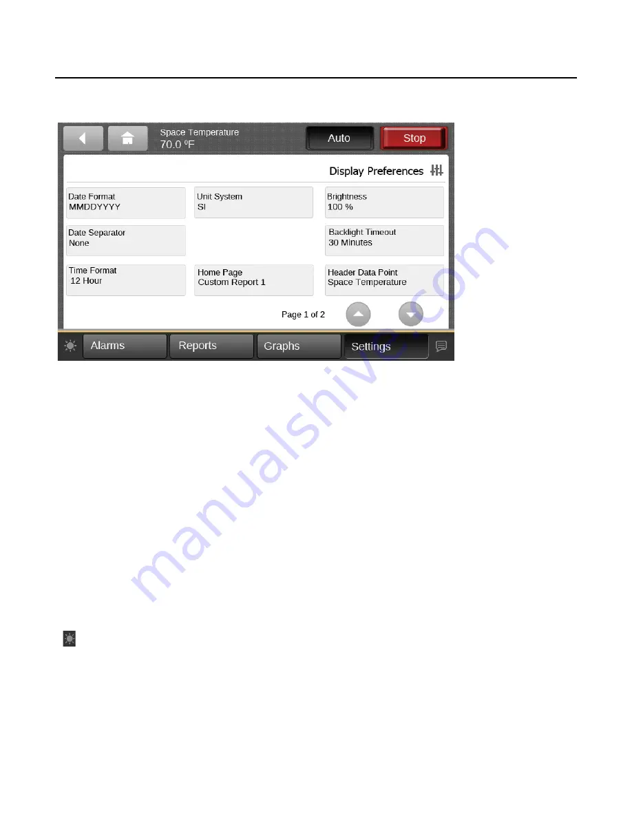
Figure 23.

Display preferences screen

Settings

RT-SVX49C-EN

33 

Date Format

Touch the 

Date Format

 button to open the associated 

screen. Three options are available to display the current 
date: MMDDYYYY, DDMMYYYY, and YYYYMMDD. 

Date Separator

Touch the 

Date Separator 

button to open the associated 

screen. Three options are available to display separators 
in the date format: None, Hyphen (-), or Slash (/).

Time Format

Touch the 

Time Format 

button to open the associated 

screen. Two options are available: 12-Hour format and 24-
Hour format (also referred to as “military time”).

Unit System

Touch the 

Unit System 

button to open the associated 

screen. Two options are available: SI (system 
international) or IP (Inch-Pound). 

Brightness

Touch the 

Brightness

 button, or the brightness icon 

(

)located at the bottom left of each screen, to open the 

associated screen. Screen brightness is measured in 
percentage. Use the keypad to enter a new brightness 
number. 

Backlight Time-out

Touch the 

Backlight Time-out

 button to open the 

associated screen. This value is measured in minutes, with 
30 being the maximum limit. Use the keypad to enter a 
backlight time-out value. This value is the amount of time 
that the display will remain lit without activity. When the 

backlight times out, users will be automatically logged off 
due to inactivity. 

Header Data Point 

Use the arrow button on the Display Preferences screen to 
advance to page 2. Touch the 

Header Data Point 

button to 

open the associated screen. The Header Data Point 
appears in the top right display area on all screens. Use the 
arrow buttons to scroll through the points. Click 

Add

 to 

move the highlighted point to the right side of the 
screen(

Figure 24, p. 34

). Click 

Save

.

Summary of Contents for Tracer TD-5

Page 1: ...on starting up and servicing of heating ventilating and air conditioning equipment can be hazardous and requires specific knowledge and training Improperly installed adjusted or altered equipment by an unqualified person could result in death or serious injury When working on the equipment observe all precautions in the literature and on the tags stickers and labels that are attached to the equipm...

Page 2: ...dures In addition some states or municipalities may have additional requirements that must also be adhered to for responsible management of refrigerants Know the applicable laws and follow them 2020 WARNING Proper Field Wiring and Grounding Required Failure to follow code could result in death or serious injury All field wiring MUST be performed by qualified personnel Improperly installed and grou...

Page 3: ...ssion Trane reserves the right to revise this publication at any time and to make changes to its content without obligation to notify any person of such revision or change Trademarks All trademarks referenced in this document are the trademarks of their respective owners Revision History RT SVX49C EN 3 Dec 2015 Added removed and updated various minor controls images and verbiage ...

Page 4: ... 5 Display for the First Time 10 Alarms 11 Active Alarms 11 Historic Alarms 12 Viewing Active and Historic Alarms 12 Alarm Icons 13 Sorting Alarms 13 Reports 14 Custom Reports 14 Creating a Custom Report 14 Editing a Custom Report 16 About 18 System Report 19 Economizer Ventilation Report 20 Compressor Report 20 Heating Report 21 Configuration Report 22 Sensor Report 22 Binary Input Report 23 Bina...

Page 5: ...s 21 VA power which it receives through a power cable The display is typically connected to J10 of the RTRM Module but it can also be powered from an alternate power source Communication RS 485 communication is provided to the TD 5 through the RTRM J10 connector Screen characteristics The 5 inch WVGA 800 x 480 resolution touch sensitive color screen is LED backlit which enables viewing in poor lig...

Page 6: ... TD 5 Installation Guide 6 RT SVX49C EN Dimensions 32 0 3 1 42 1 7 1 154 0 1 6 147 0 8 5 106 4 2 4 115 3 5 4 Note The power cable ispermanently attachedto the TD 5 display The power connector provides strain relief and ...

Page 7: ...st and strong water protection PN X19070632020 Display color TFT LCD 800 nits brightness 16 bit color Agency Compliance UL916 PAZX Open Energy Management Equipment UL94 5V Flammability FCC CFR Title 47 Part 15 109 Class A Limit 30 MHz 4 GHz CE EMC Directive 2004 108 EC Supported Languages The TD 5 display supports 26 built in languages For help on how to select a specific language for the display ...

Page 8: ...op button to stop the unit from running and prevent it from starting Main Display Area This area serves as the main task area in which you can view custom graphics create reports view and take action on alarms and view or change display settings Bottom Display Area The bottom display area contains functional buttons that provide a link to the appropriate screen Screen brightness settings Touch thi...

Page 9: ...a VESA Mounting Bracket The Tracer TD 5 can be mounted near the RTRM module in the control panel or remotely mounted up to 328 ft 100 m by using a field suppled 75 mm VESA mount Remote mounting requires the following additional field supplied components A power source that will supply 24 VAC to the display Power cables Many commercial 75mm VESA mounting brackets are available which range from a si...

Page 10: ... for TD5 it doesn t matter which one is powered first Upon successful power up the TD 5 Display will default to the configured home screen The System Report is the factory default On every power cycle a touchscreen calibration screen is presented briefly If no touches are registered the calibration process does not start and the TD5 continues to the home screen Refer to the touchscreen calibration...

Page 11: ...in order for points in alarm to appear in the Active Alarms screen The number of active alarms is displayed in the top right portion of the screen When an active alarm is present the alarm button at the bottom of the screen will flash The Alarms screen defaults to Active Alarms The Active Alarms button has a shaded appearance which indicates that you are viewing active alarms Figure 3 Active alarm...

Page 12: ...active alarms will clear automatically when the condition causing the alarm is removed Others will latch and only clear if the condition causing the alarm is removed and the Reset Alarms is pressed Historic alarms These are alarms are no longer active The alarm conditions have been corrected Alarm Severity A color code icon representing the severity of each alarm is shown under the severity column...

Page 13: ...mid Setpoint Failure Airflow Sensor Fail Min OA Flow Setpoint Fail Space Pressure Setpoint Fail Space Pressure Sensor Fail Heating High Temp Limit Open Flame Rollout Switch Open Inducer Proving Switch Fail No Flame Sensed on heat call Flame Sensed w Gas Valve Off Gas Heat Module Failure Economizer Actuator Fault Morning Warmup Setpoint Fail SA Reset Amount Failure SA Temp Cool Setpoint Fail SA Tem...

Page 14: ...ut Custom Report 2 Compressor Report Sensor Report Custom Report 3 Operating Modes Configuration Report Economizer Ventilation Report Heating Report Binary Input Report Binary Output Report Figure 5 Reports screen Custom Reports You can create up to three custom reports using the Tracer TD 5 Display Creating a Custom Report 1 Navigate to the Reports screen then touch one of the three custom report...

Page 15: ...dding values to your report When you are finished touch the Save button The Custom Report screen populated with your selected values appears Figure 7 p 16 To view the items in the selected list touch a value in this list and use the up and down arrows to the right of the list To change the location of an item in the list select the item and then use the up and down arrows above the table to move t...

Page 16: ...an be rearranged according to personal preference by using the editing tools as described in Editing a Custom Report For example you created the custom report shown in Figure 7 p 16 but would prefer to move item Diagnostic Space Static Pressure Failure to the top left portion of the report To change the order for the example described above 1 Touch the Edit button on the Custom Report screen Scrol...

Page 17: ... Note On the TD 5 display report items are ordered from left to right with the first item appearing at the top left portion of the screen Up to nine items can appear on each Custom Report screen Up to nine items can appear on each Custom Report page EachCustomReportcanhaveuptosevenpagesfor a total of 63 unique items The model in Figure 9 p 17 depicts a custom report screen with the first nine item...

Page 18: ...is the name that was entered Unit Name ReliaTel RTRM Software Version 6200 0123 1 00 RTVM Software Version 6200 0124 01 00 VSM Software Version 6200 0628 01 00 RTOM Software Version 6200 0124 01 00 RTAM Software Version 6200 0126 01 00 RTEM Software Version 6200 0134 01 00 RTDM Software Version 6200 0531 01 00 BAS Interface Software Version BAS 01 00 Display User Interface Software Version 6200 06...

Page 19: ...ode Manual Auto Economizing Enabled Disabled Ventilation Control Fixed DCV DCV Demand Control Ventilation Variable Speed Compressor Volts XXX V Variable Speed Compressor Capacity XXX X Fresh Air Measurement Installed Not Installed Heating Type None Electric Gas Hydronic Cooling Stages Configured X Available Heating Stages X Supply Fan Starts XXXXX Supply Fan Running Time HHHHH MM Space Pressure X ...

Page 20: ... Outdoor Air Flow Deadband XXXXX CFM LPM Exhaust Fan Starts XXXXXX Exhaust Fan Running Time HHHHH MM Exhaust Damper Position Open XXX Outdoor Fan A Output Space Pressure XX XX IWC cmWC Active Space Pressure Setpoint XX XX IWC cmWC Space Pressure Deadband XX XX IWC cmWC Ventilation Override Pressurize Input Open Closed Ventilation Override Purge Input Open Closed Ventilation Override Exhaust Input ...

Page 21: ... Switch Input Open Closed IGN Temp Limit Input Open Closed IGN Flame Rollout Input Open Closed IGN Inducer High Output Off On IGN Inducer Low Output Off On Reheat Entering Evap Temp XXX X F C Reheat Valve Position XXX Reheat LPC Input Enabled Disabled Supply Air Temp XXX X F C Active Space Temp XXX X Active Space Cooling Setpoint XXX X F C Defrost Status Ckt 1 Inactive Defrosting Defrost Status Ck...

Page 22: ...indmill Prevention Disable Enable Gas IGN Module 1 Staged Modulating True Supply Air Reporting Disable Enable Supply Air Tempering Input Disable Enable Gas IGN Module 2 Installed Not Installed Manual Enthalpy Override Disable Enable Lead Lag Configuration Input Disable Enable Outdoor Air Flow Compensation Disable Enable Outdoor Fan Cycling Input Lower Normal Programmable Zone Sensor Installed Not ...

Page 23: ...RTOM Freezestat Input Open Closed Smoke Detector Input Open Closed RTOM Reheat Humidistat Input Open Closed Changeover Switch Input Cooling Heating VSM Compressor 3 Disable Input Enabled Disabled Compressor 3 Proving Input Open Closed RTVM Exhaust Fan Proving Input Open Closed Reheat LPC Input Enabled Disabled IGN IGN Pressure Switch Input Open Closed IGN Temp Limit Input Open Closed IGN Flame Rol...

Page 24: ...igure 12 Operating modes report details screen Reports 24 RT SVX49C EN Note Operating Modes The operating Mode page shall show the user the general operation of the unit and what modes it is operating in ...

Page 25: ...choosing the line color Touch the Graphs button in the bottom display area to view the Graphs screen Figure 13 p 25 The Graphs screen contains twelve buttons that allow you to view and edit a particular graph There are four custom graphs and 8 standard graphs Figure 13 Graphs screen Creating a Custom Graph 1 Navigate to the Graphs screen then touch an available data graph button The Custom Graph s...

Page 26: ...ich reflects the selected values Figure 15 Adding data logs to the custom graph 7 Use the Edit Graph screen to modify the graph Touch the Edit button that corresponds with the value that you want to change Only one value can be edited at a time Figure 16 Edit graph screen after values have been added 8 From the Edit screen you can choose which Y axis to display the value a color and whether or not...

Page 27: ... the graph at anytime Touch the zoom in icon and zoom out icon to either increase or decrease the viewable time frame This action also enables back and forward arrows that allow you to view data at various times of the day Figure 18 Viewing the graph Editing the Y Axis The default values on the right and left Y axes can be changed according to your specifications 10 Touch the Edit Y Axis button lo...

Page 28: ... shall be 8 standard graphs The standard graphs are below Table 10 Standard graphs Space Temperature Economizer Compressor Outside Air Ventilation VAV Humidity Heat Pump CO2 Space Temperature The table below describes the data in the System Status graph Data Point Line Color Axis Active Space Temp Setpoint Blue Left Active Space Temp Green Left Supply Air Temp Black Left Return Air Temperature Red...

Page 29: ...Black Left Outdoor Air Flow Pink Left Outdoor Air Damper Yellow Right Outdoor Air Temp Purple Right CO2 Graph The table below describes the data in the graph Data Point Line Color Axis Active Upper CO2 Limit Setpoint Red Left Active Lower CO2 Limit Setpoint Black Left Space CO2 Green Left Outdoor Air Damper Yellow Right Humidity Graph The table below describes the data in the graph Data Point Line...

Page 30: ...s button in the bottom display area to view the Settings screen Three categories for settings appear on the screen Control Settings Display Settings Security Settings Figure 20 Settings screen Setpoints Touch the Setpoints button to view the Setpoints screen Touch the arrow buttons to move between screens Figure 21 Setpoints screen ...

Page 31: ...Setpoint XX Econ Reference Enthalpy Setpoint XX X BTU lb Econ Dry Bulb Enable Setpoint XXX X F C Exhaust Fan Enable Setpoint XX Design Min OA flow Setpoint XXXXX cfm DCV Min OA Flow Setpoint XXXX cfm Min OA Flow Deadband XXXXX cfm Design Min OA Damper Pos Setpoint 100 Fan XX Design Min OA Damper Pos Setpoint Mid Fan XX Design Min OA Damper Pos Setpoint Min Fan XX DCV Min OA Damper Pos Setpoint 100...

Page 32: ...uto Display Settings Screen The selections in this category contain settings that affect the way in which information is displayed on all of the TD 5 display screens From each screen the current settings can be viewed To change a setting touch the preferred value Display Preferences Touch the Display Preferences button to open the associated screen Figure 23 p 33 On this screen all available optio...

Page 33: ...e brightness icon located at the bottom left of each screen to open the associated screen Screen brightness is measured in percentage Use the keypad to enter a new brightness number Backlight Time out Touch the Backlight Time out button to open the associated screen This value is measured in minutes with 30 being the maximum limit Use the keypad to enter a backlight time out value This value is th...

Page 34: ...ouching buttons To calibrate the touchscreen carefully touch each of the 5 targets presented It is important that the targets are touched accurately or this will cause problems touching buttons after calibration It is recommended but not required to use a pencil eraser to do this since it s easier to control the exact location of the touch Do not use anything hard to press on the touchscreen since...

Page 35: ...ection Frequency Collection frequency sets the time interval that the Graph Data is saved and displayed on the graph The faster the sample rate the lower the duration The default of 30 seconds shall provide 3 5 days of data collection Figure 26 Collection frequency ...

Page 36: ...will display when the home button is touched Figure 27 Home page screen Language Touch the Language button or the language icon located at the bottom right of each screen to open the open the Language screen Twenty six languages are available and represented on the selection buttons Select a language that you want displayed on each TD 5 screen and then touch Save See Language p 36 Figure 28 Langua...

Page 37: ...te and time screen Clean Touchscreen Touch the Clean Touchscreen button to safely clean the TD 5 touchscreen using any brand of common household glass cleaner When this button is touched the screen background color becomes black allowing dirt and fingerprints to become more visible It also displays a countdown timer five to zero seconds Touch the screen anytime within the 5 second countdown to beg...

Page 38: ...ource and that the power source is in working condition After powering up the TD 5 displays a message that it is not communicating Controller not powered up Replace cable if necessary Power up the controller if necessary No data available in custom report Data has not yet been defined for the report Add data to report See Creating a Custom Report p 14 Blank display TD 5 has gone into a low power m...

Page 39: ......

Page 40: ...fications without notice We are committed to using environmentally conscious print practices Trane and American Standard create comfortable energy efficient indoor environments for commercial and residential applications For more information please visit trane com or americanstandardair com RT SVX49C EN 02 Apr 2020 Supersedes RT SVX49B EN Dec 2015 ...

Reviews: