16
PKG-SVX027C-EN
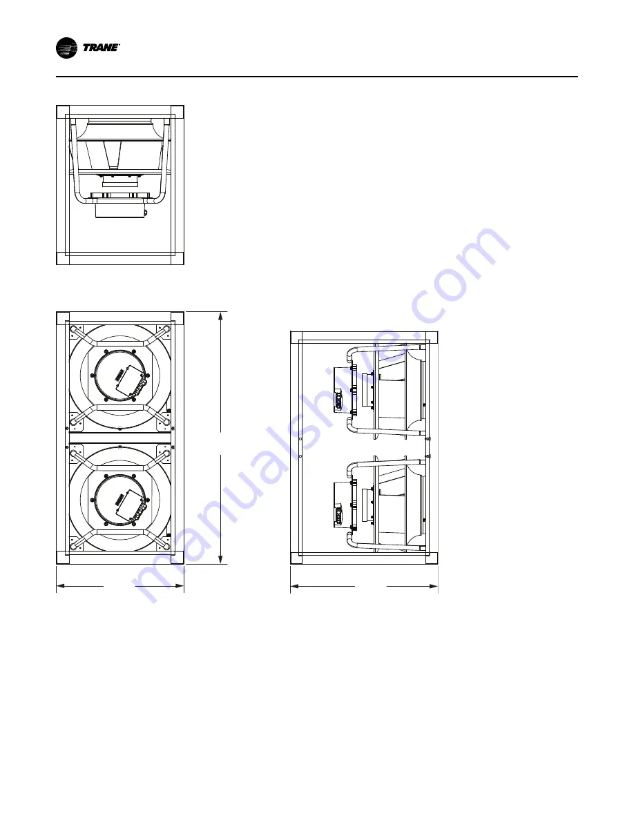
Figure 4. Fan assembly footprint (in mm/inches)
FRONT VIEW
[1384]
54.49
[876]
34.50
[700]
27.56
SIDE VIEW
TOP VIEW
D
Diim
me
en
nssiio
on
na
all D
Da
atta
a
Page 1: ...ic knowledge and training Improperly installed adjusted or altered equipment by an unqualified person could result in death or serious injury When working on the equipment observe all precautions in t...
Page 2: ...a ar r p pr ro op pe er r P PP PE E f fo or r t th he e j jo ob b b be ei in ng g u un nd de er rt ta ak ke en n c co ou ul ld d r re es su ul lt t i in n d de ea at th h o or r s se er ri io ou us s...
Page 3: ...lw wa ay ys s f fo ol ll lo ow w l lo oc ca al l r re eg gu ul la at ti io on ns s Copyright This document and the information in it are the property of Trane and may not be used or reproduced in who...
Page 4: ...Arrangements 32 Water Temperature Requirements 32 Water Piping Verification 32 Refrigerant System 32 Interconnecting Piping 33 Preliminary Refrigerant Charging 34 Charging and Wiring the Unit 34 Fan I...
Page 5: ...Compressor Control 52 Waterside Components 52 Water Purge 52 Water Piping Options 52 Basic Water Piping 52 Water Regulating Valve WRV optional 52 Water Flow Switch Option 53 Waterside Economizer Opti...
Page 6: ...mpressor Failure Diagnosis and Replacement 69 Components 70 Cleaning Coil Fin 70 Sequence of Operations 72 Recognizing ScaleBreak s saturation point 72 Circulation Pump Setup 72 Cleaning Instruction 7...
Page 7: ...ents Left or right hand power connections Left or right hand water connections Factory installed options The hermetically sealed scroll compressor motors utilize internal motor protection and time del...
Page 8: ...rols points provided Optional Controls Optional controls include a disconnect switch dirty filter switch water flow switch supply air temperature reset or external setpoint inputs Morning warm up oper...
Page 9: ...Left Hand Connections R Right Hand Connections Digit 18 Unit Water Connections 1 Victaulic 2 Pipe Connections Digit 19 Air Discharge H Horizontal Discharge V Vertical Discharge Digit 20 Electrical Con...
Page 10: ...4 6 4 6 4 6 4 6 4 6 4 6 4 Minimum Design cfm c 11000 11000 13750 13750 16500 16500 19250 19250 22000 22000 Maximum Design cfm 16000 16000 20000 20000 24000 24000 28000 28000 32000 32000 Refrigerant Ch...
Page 11: ...formance is rated at 80F EDB 67F EWB with 85 EWT for water cooled performance and 95F Ambient for air cooled performance 3 EER IEER and AHRI Net Cooling Capacity are tested in accordance with the AHRI...
Page 12: ...5 Waterside economizer coil physical data Model Unit Size Rows FPF Height Length MSC 40 Ton 4 150 75 49 MSC 50 Ton 4 150 75 65 MSC 60 Ton 4 150 75 73 MSC a 70 Ton 4 150 75 38 4 150 75 64 MSC a 80 Ton...
Page 13: ...unit if necessary Allow minimum recommended clearances for routine maintenance and service Allow space at end of the unit for servicing Refer to the unit submittals for dimensions See also the Service...
Page 14: ...nce that the damage did not occur after delivery Repair Notify the appropriate sales representative before arranging unit installation or repair I Im mp po or rt ta an nt t Do not repair unit until th...
Page 15: ...30 Condenser pipe Connections Table 7 Unit dimensions in inches Model Width Height Depth 40 40L 96 a 84 69 50 50L 96 a 84 69 60 60L 96 a 84 69 70 70L 127 a 84 69 80 80L 127 a 84 69 a Does not include...
Page 16: ...16 PKG SVX027C EN Figure 4 Fan assembly footprint in mm inches FRONT VIEW 1384 54 49 876 34 50 700 27 56 SIDE VIEW TOP VIEW D Di im me en ns si io on na al l D Da at ta a...
Page 17: ...PKG SVX027C EN 17 Figure 5 Variable speed compressor assembly footprint in mm inches TOP VIEW FRONT VIEW SIDE VIEW 870 34 26 749 29 50 700 27 56 D Di im me en ns si io on na al l D Da at ta a...
Page 18: ...18 PKG SVX027C EN Figure 6 Starter cassette assembly footprint in inches 876 34 50 700 27 56 TOP VIEW FRONT VIEW SIDE VIEW D Di im me en ns si io on na al l D Da at ta a...
Page 19: ...Model Width Split Coil Width Height Depth 40 40L 96 a N A 84 34 5 50 50L 96 a N A 84 34 5 60 60L 96 a N A 84 34 5 70 70L b 127 a 77 84 34 5 50 84 34 5 80 80L b 127 a 77 84 34 5 50 84 34 5 a Does not...
Page 20: ...736 28 99 Service Clearances Table 9 Service code clearance requirements Side Distance in mm Purpose Front 42 1066 Fans Compressors Condensers Refrigeration access Left Left Hand Starter 42 1066 NEC...
Page 21: ...umber Fixed Spd FS Condensing Unit Cassette Num ber Var Spd VS Condensing Unit Cassette Total Condensing Unit Weight 40 Ton 70 x 84 x 95 5 2933 34 5 x 29 5 x 27 6 1 385 1 335 720 50 Ton 70 x 84 x 95 5...
Page 22: ...ed Tonnage Overall dimensions Unit Weight lbs Evaporator Cassette Total Weight of Cassette excl Economizer 70 Ton a 70 x 84 x 127 4545 34 5 x 84 x 77 1032 34 5 x 84 x 50 620 80 Ton a 70 x 84 x 127 454...
Page 23: ...ances may still require the Evaporator Cassette to be disassembled to move it into the mechanical room For disassembly instructions please contact MJC Sales at 770 988 8338 Installation Preparation Be...
Page 24: ...FAN 3 4 SPACER EVAP DOOR FAN 1 2 FAN 5 WATER IN WATER OUT STARTER CONTROL 50T Evap section 30T Evap section EVAP DOOR Installation Summary The steps below provide a summary of installation steps for i...
Page 25: ...acer cassette 3 Add variable speed compressor A condensing unit 4 Add fixed speed compressor B condensing unit 5 Add fixed speed compressor C condensing unit I In ns st ta al ll la at ti io on n M Me...
Page 26: ...SVX027C EN 6 Add starter control panel cassette 7 Add fans 1 and 2 fan cassette 8 Add fan spacer cassette 9 Add fans 3 and 4 fan cassette I In ns st ta al ll la at ti io on n M Me ec ch ha an ni ic c...
Page 27: ...ompressor spacer to evaporator first 3 Secure with intelleclamps 4 Unbraze caps from both evaporator and compressor first Line up compressor A piping to the corresponding evaporator holes 5 Push compr...
Page 28: ...erything for compressor A 8 Unbraze caps and line up compressor B 9 Push compressor B in and clamp down to compressor A using intellaclamps 10 Build IC pipe and braze compressor B I In ns st ta al ll...
Page 29: ...e up compressor C 12 Push compressor C in and clamp down to compressor B using intellaclamps 13 Build IC pipe and braze compressor C 14 Unbraze caps and line up compressor D I In ns st ta al ll la at...
Page 30: ...g gh h P Pr re es ss su ur re e W Wa at te er r F Fa ai il lu ur re e t to o f fo ol ll lo ow w i in ns st tr ru uc ct ti io on ns s b be el lo ow w c co ou ul ld d r re es su ul lt t i in n d de ea a...
Page 31: ...nnections are located on the right or left hand side of the unit depending upon configuration required All field installed piping must conform to applicable local state and federal codes To complete c...
Page 32: ...ength of supply and return pipes Multi story buildings may use a direct return system with balancing valves at each floor Install the supply riser and its return in close proximity Furnish both with p...
Page 33: ...ion and helps prevent POE compressor oil contamination This will also indicate large leaks if vacuum does not hold below 400 microns and hold for 2 hours Complete Leak Test and Evacuation for procedur...
Page 34: ...er ra an nt t i is s n ne ec ce es ss sa ar ry y y yo ou u M MU US ST T w we ea ar r a al ll l P Pe er rs so on na al l P Pr ro ot te ec ct ti iv ve e E Eq qu ui ip pm me en nt t P PP PE E i in nc cl...
Page 35: ...r and communication wiring Figure 20 Fixed speed compressor power and communication wire routing Figure 21 Compressor communication terminations N No ot te e Pluggable connectors are color coded and i...
Page 36: ...startup More charge will be added after compressors are started Use an accurate scale to measure and record preliminary amount of refrigerant added to each circuit 9 Record charge amount added 10 If t...
Page 37: ...e routing Figure 26 Fan power and communication wiring Figure 27 Fan communication terminations pluggable connectors are color coded for ease of installation Figure 28 Fan power terminations I In ns s...
Page 38: ...hree fan diameters Use 3 flexible duct connection on discharge ductwork Run the ductwork straight from the opening Extend remaining ductwork as far as possible without changing size or direction Do no...
Page 39: ...as sk ks s 1 With main power still dis connected a Circuit breakers on b Place fuses in fan fuse holder c One fuse pulled on control power transformer primary d Fan fuse holders connected ie closed e...
Page 40: ...TD 7 Installation on front 2 Attach brackets on back side of Low Voltage door to secure the TD 7 to the door Figure 33 TD 7 Installation on back with brackets I In ns st ta al ll la at ti io on n M M...
Page 41: ...o u us se e c co op pp pe er r c co on nd du uc ct to or rs s c co ou ul ld d r re es su ul lt t i in n e eq qu ui ip pm me en nt t d da am ma ag ge e a as s t th he e e eq qu ui ip pm me en nt t w w...
Page 42: ...standard rating as the maximum Table 15 Number of compressors MSC SCWMN 04L SCWMN 40 SCWMN 05L SCWMN 50 SCWMN 06L SCWMN 60 SCWMN 07L SCWMN 70 SCWMN 08L SCWMN 80 66cc ZPV0662 1 0 1 0 1 0 1 0 1 0 96cc...
Page 43: ...080F 208 230 60 3 187 253 370 3 450 400 3 55 77 340 1 84 5 6 15 18 6 SCWMN08L4 460 60 3 414 506 156 2 175 175 3 23 72 110 1 30 5 6 15 9 SCWMN0804 460 60 3 414 506 193 7 250 200 3 23 72 110 1 60 5 6 15...
Page 44: ...21 Compressor electrical data 40 to 80 tons Tonnage Model Number Nameplate Voltage Compressor EA Fixed Speed Variable Speed Qty RLA LRA Qty Max Input A 40 SCWMN04LF 208 230 60 3 1 55 77 340 1 56 SCWMN...
Page 45: ...rtion into ductwork If a specific head assembly or remote location is desired then this material will be the responsibility of the installer There are two pressure transducers mounted on the side of t...
Page 46: ...nu uf fa ac ct tu ur re er r s s l li it te er ra at tu ur re e f fo or r a al ll lo ow wa ab bl le e w wa ai it ti in ng g p pe er ri io od ds s f fo or r d di is sc ch ha ar rg ge e o of f c ca ap...
Page 47: ...he unit use the convention of connecting zone sensor terminals to like numbered unit terminals 1 to 1 2 to 2 etc The connection detail is shown on the unit wiring diagrams which are located in the uni...
Page 48: ...right hand corner the unit can be put into Auto to perform normally or Stop to perform a controlled shutdown and keep the unit off Water Flow Control With compatible piping configurations the unit can...
Page 49: ...ance of maintaining the proper superheat cannot be overemphasized Accurate measurements of superheat will provide the following information How well the expansion valve is controlling the refrigerant...
Page 50: ...fferential pressure warn the user if a high discharge pressure condition occurs activate the VS compressor Limit Condition control function The suction pressure sensor is used by the Unit Controller t...
Page 51: ...seconds The compressor then runs at whatever speed commanded by the Unit Controller Similarly when the 1U1 drive receives a Controlled Stop signal it runs the compressor at 3600 rpm for 60 seconds the...
Page 52: ...re es s w wh hi ic ch h r re es su ul lt t f fr ro om m u un nt tr re ea at te ed d o or r i im mp pr ro op pe er rl ly y t tr re ea at te ed d w wa at te er r o or r s sa al li in ne e o or r b br r...
Page 53: ...e When the MSC Operating Mode is set to BAS HEAT the UC600 controller ends any Cooling Mode operation Mechanical and or Water Side Economizer and transitions to control Discharge Air Temperature to th...
Page 54: ...in the name example XM30 is the IMC bus address which is set using the rotary switches on the module Remotely mounted in the compressor cassettes the following modules are used XM30 7 Entering Leaving...
Page 55: ...upied XM70 1 PI Air Filter Differential Pressure Honeywell Pressure Sensor BO1 Heat Output 1 Open Off Closed On BO2 Heat Output 2 Open Off Closed On BO3 Heat Output 3 Open Off Closed On BO4 AO1 UI9 Su...
Page 56: ...sure Sensor Local 0 5 Vdc 0 PSI 4 5 Vdc 667 PSI AO2 UI2 Compressor 1 Suction Pressure 0 5 Vdc 0 PSI 4 5 Vdc 667 PSI AO3 UI3 Compressor 1 Suction Temperature 10K Ohm Resistor Trane Type 2 AO4 UI4 Compr...
Page 57: ...Figure 39 Home screen Screen Element Description A Home button B Displays the local Auto Stop button and displays the occupancy Heat Cool Mode and Unit Information C Displays information about the Air...
Page 58: ...n arrows in the bottom right to scroll through the report Figure 41 All points report Starting the Unit Before starting the unit ensure that All checks are complete Alarms are cleared Compressors that...
Page 59: ...setpoint 10 in H20 Occupied Offset DAT Reset Units Only Determines the occupied cooling and heating setpoints when the unit resets the discharge air temperature off either return or space temperature...
Page 60: ...tu up p report locate the point in the menu Use the arrows to scroll through the report if needed 4 Use the up and down arrows to change the value or press inside the box and type in the desired setp...
Page 61: ...it ty y f fo or r e eq qu ui ip pm me en nt t f fa ai il lu ur re es s w wh hi ic ch h r re es su ul lt t f fr ro om m u un nt tr re ea at te ed d o or r i im mp pr ro op pe er rl ly y t tr re ea at t...
Page 62: ...prevent leaks Verify that all ductwork conforms to NFPA 90A or 90B and all applicable local codes Water Cooled Unit Piping Verify condensate drain water piping drain plugs economizer header strainer p...
Page 63: ...ressors running SLOWLY meter remaining R 410A into the suction line from the LIQUID charging connection N NO OT TI IC CE E C Co om mp pr re es ss so or r D Da am ma ag ge e O Ov ve er rc ch ha ar rg g...
Page 64: ...d Programming Guide PKG SVP01 EN for available unit operating setpoints and instructions A copy ships with each unit For units with VFD option see installer guide that ships with each VFD Startup Log...
Page 65: ...ge e c ca ap pa ac ci it to or rs s b be ef fo or re e s se er rv vi ic ci in ng g c co ou ul ld d r re es su ul lt t i in n d de ea at th h o or r s se er ri io ou us s i in nj ju ur ry y D Di is sc...
Page 66: ...urer s instructions regarding product use 6 Immediately rinse the drain pan thoroughly with fresh water to prevent potential corrosion from the cleaning solution 7 Allow the unit to dry thoroughly bef...
Page 67: ...it nameplate design pressures If testing complete system low side design pressure is maximum 3 Check piping and or components as appropriate for leaks 4 Recommend using electronic detector capable of...
Page 68: ...cuum pump After several minutes the gauge reading will indicate the maximum vacuum the pump is capable of pulling Rotary pumps should produce vacuums of 100 microns or less N NO OT TI IC CE E M Mo ot...
Page 69: ...ium indicates the true amount of moisture left in the system It indicates that no leaks are present and the system is properly evacuated State of equilibrium indicates the true amount of moisture left...
Page 70: ...cl le ea an ne er rs s w wi it th h a a p pH H v va al lu ue e g gr re ea at te er r t th he en n 8 8 5 5 a af ft te er r m mi ix xi in ng g w wi it th ho ou ut t u us si in ng g a an n a al lu um mi...
Page 71: ...us se e T Tr ra an ne e r re ec co om mm me en nd ds s g gl ly yc co ol l p pr ro ot te ec ct ti io on n i in n a al ll l p po os ss si ib bl le e f fr re ee ez zi in ng g a ap pp pl li ic ca at ti i...
Page 72: ...it needs to add additional product to complete the cleaning If its circulated for the recommended time duration the pH did not go above 4 and its not visually seeing any additional bubbling and foamin...
Page 73: ...anger If the exit point is lower than the top of the plate pack position the hose at a higher point This action will insure the entire plate pack is flooded and ScaleBreak MP comes in contact with all...
Page 74: ...l duration of cleaning time and safety precautions necessary for handling the cleaning agent Piping Components Water Valves W WA AR RN NI IN NG G H Ha az za ar rd do ou us s V Vo ol lt ta ag ge e w w...
Page 75: ...traps drain pan and drainage holes Remove algae and or any airflow obstructions 4 Check the liquid line sight glasses during operation Bubbles in the sight glasses indicate a possible shortage of ref...
Page 76: ...harge and suction line access valves When the unit has stabilized after operating approximately 15 minutes at full load record suction and discharge pressures System malfunctions such as low airflow l...
Page 77: ...Ensure that the XM Module is up and talking to the UC600 System has no charge Verify that the system has a refrigerant charge Sensor has failed Manual Reset required once the sensor is in a Normal St...
Page 78: ...tate User must toggle the Compressor 1 4 Failure Reset Diagnostic Compressor 1 4 Suction Pressure Sensor Failure In Fault Notification Class Action Reason Typical Causes Reset Required HVAC Critical A...
Page 79: ...n Temperature Sensor Failure In Fault Notification Class Action Reason Typical Causes Reset Required HVAC Critical Alarm Compressor will be locked out and prevented from running until this sensor is i...
Page 80: ...ion which indicates The temperature sensor is reading either above is maximum value or below is minimum value resulting in an Alarm Condition after 3 point updates Sensor is not wired properly Verify...
Page 81: ...ver Charge on unit Malfunctioning TXV Dirty Condenser tubes TXV Bulb is not strapped tightly to suction line Too little air across the evaporator Manual Reset required once the issue is resolved User...
Page 82: ...from exceeding the Condenser Control Pressure Setpoint Head Pressure has exceeded the condenser Control Pressure Setpoint High Condenser Water Temperature Malfunctioning TXV Non Condensable in the re...
Page 83: ...no longer exists Note These warnings are generated to alert the end user to a potential condition Table 31 Supply fan alarms Supply Fan 1 6 Failure In Fault Notification Class Action Reason Typical C...
Page 84: ...ency stop binary input is open None alarm clears once sensor is in a normal state Discharge Air Temperature In Fault Notification Class Action Reason Typical Causes Reset Required HVAC Critical Alarm...
Page 85: ...et Required HVAC Critical Alarm Unit will shut down and be prevented from running until this sensor is in a normal state The discharge air temperature is less than or equal to the Discharge Air Low Te...
Page 86: ...ading either above its maximum value or below is minimum value resulting in a Fault Condition after 3 point updates Sensor is not wired properly Verify sensor wiring to the XM Module XM Module is not...
Page 87: ...rs on the unit not related to the Fans or Compressors and will shut down the unit Table 33 General unit warning Diagnostic Dirty Air Filter In Alarm Notification Class Action Reason Typical Causes Res...
Page 88: ...value or below is minimum value resulting in a Fault Condition after 3 point updates Sensor is not wired properly Verify sensor wiring to the XM Module XM Module is not communicating Ensure that the...
Page 89: ...equired Affects the alarm for Dirty Strainer preventing alarm from working properly The Pressure sensor is reading either above is maximum value or below is minimum value resulting in a Fault Conditio...
Page 90: ...dule None alarm clears once sensor is in a normal state Compressor 1 E Stop Shutdown Command In Fault Notification Class Action Reason Typical Causes Reset Required HVAC Service Required Output may no...
Page 91: ...nce sensor is in a normal state Supply Fan 1 6 Start Stop Command In Fault Notification Class Action Reason Typical Causes Reset Required HVAC Service Required Output may not function properly The UC6...
Page 92: ...For more information please visit trane com or tranetechnologies com Trane has a policy of continuous product and product data improvements and reserves the right to change design and specifications w...