20
CTV-SVX06J-EN
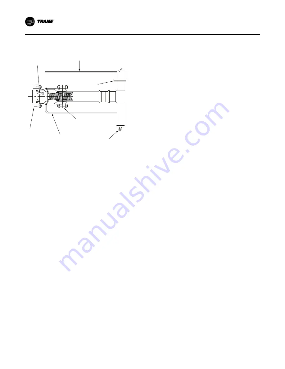
Figure 19.
RuptureGuard external vent line and drip
leg (not provided)
Metal
RuptureGuard
disk
Purge
exhaust
Flange
Vent to
outdoors
Flange
Drain
line
Chiller
flange
Drain
valve
Drip
leg
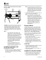
Important:
The purge exhaust line MUST be connected to the
downstream side piping to vent purge exhaust out the vent line
to the outdoors; it may need to be extended to the drip leg.
Field-acquired tubing may be required to extend to the
field-supplied vent piping, depending on distance. Do NOT
create a U-trap in the purge exhaust line; this line MUST be
sloped from purge (highest point toward field-supplied piping,
lower point toward connection) to allow proper draining of any
condensation.
N
No
otte
ess::
•
Use Loctite
®
242 or Loctite
®
277 on all
threaded joints on chillers charged with
refrigerant; use of other pipe thread sealants
is NOT recommended. Ensure all threaded
pipe joints are properly cleaned and
prepared before assembly. An alternative to
the use of Loctite
®
is to thread and weld the
inlet adapter to the pipe. Care must be taken
to ensure that the flange mating surface
remains flat. Do NOT weld on the Inlet
Adapter flange while connected to the
RuptureGuard
™
.
•
The drip leg is REQUIRED. The drip leg
should be a minimum of 1 gal (3.8 L)
capacity and must be drained periodically
for proper chiller purge operation.
Install Pressure Gauge and
Excess Flow Valve
1. Screw the 1/4-in. (6.4 mm) NPT pressure gauge and
1/4-in. (6.4 mm) NPT excess flow valve into the
threaded ports located in the disk-valve interspace
of the valve body.
N
No
otte
e:: The excess flow valve must be installed to
maintain the downstream side of the rupture
disk at atmospheric pressure to assure proper
operating conditions for the disk. Mount the
excess flow valve as close to horizontal as
possible (see ). Do NOT use vertical ports for
the excess flow valve.
2. If required, screw the 1/4-in. (6.4 mm) NPT pressure
switch in the remaining threaded port.
N
No
otte
e:: Use Loctite
®
242 or Loctite
®
277 on ALL
threaded joints on chillers charged with
refrigerant; use of other pipe thread sealants
is NOT recommended. Ensure all threaded
pipe joints are properly cleaned and prepared
before assembly. An alternative to the use of
Loctite
®
is to thread and weld the Inlet
Adapter to the pipe. Care must be taken to
ensure that the flange mating surface
remains flat. Do NOT weld on the Inlet
Adapter flange while connected to the
RuptureGuard
™
.
Pressure Switch
A calibrated pressure switch, used to signal a disk
rupture, comes standard with each RuptureGuard
™
(installation is optional). When a disk ruptures, the
pressure inside the valve holder section increases to
the chiller pressure. The increased pressure changes
the position of the switch’s SPDT contacts. See
for detailed switch ratings.
The use of the binary output signal from the switch is
specific to each application. Some typical ways the
switch output can be used are:
•
provide the switching action to activate a local or
remote audible or visual alarm.
•
provide an alarm contact closure to a building
management system, such as Tracer
™
.
•
wired in series with other safety controls to shut
down pumps, boilers or other ancillary system
components that may be contributing to the high
pressure condition.
Leak Test
1. Leak test the RuptureGuard
™
installation using dry
nitrogen and soap; pressure test the
RuptureGuard
™
at 5 psig (34.5 kPaG).
2. Finalize with 5 psig (34.5 kPaG) dry nitrogen until
chiller commissioning.
Installation Complete Checklist
☐
All parts received; if not, contact supplier using
telephone number listed in the packing lists.
☐
For a new chiller, release the nitrogen holding
charge from the chiller to the outdoors.


