background image

CTV-SVX06J-EN

17

N

NO

OT

TIIC

CE

E

E

Eq

qu

uiip

pm

me

en

ntt D

Da

am

ma

ag

ge

e!!

M

Miix

xiin

ng

g rre

effrriig

ge

erra

an

nttss o

orr o

oiillss cco

ou

ulld

d rre

essu

ulltt iin

n

e

eq

qu

uiip

pm

me

en

ntt d

da

am

ma

ag

ge

e iin

nccllu

ud

diin

ng

g b

be

ea

arriin

ng

g d

da

am

ma

ag

ge

e,,

iin

nttrro

od

du

uccttiio

on

n o

off a

acciid

dss iin

ntto

o tth

he

e cch

hiilllle

err,, o

orr cco

on

nttiin

nu

uo

ou

uss

p

pu

urrg

ge

e p

pu

um

mp

p--o

ou

utt iin

n h

hiig

gh

h--h

he

ea

ad

d//h

hiig

gh

h a

am

mb

biie

en

ntt

a

ap

pp

plliicca

attiio

on

nss..

C

Ce

en

nT

Trra

aV

Va

acc™

™ cch

hiilllle

errss a

arre

e m

ma

an

nu

uffa

accttu

urre

ed

d w

wiitth

h

d

diiffffe

erre

en

ntt rre

effrriig

ge

erra

an

ntt//o

oiill ssy

ysstte

em

mss:: 1

1)) cch

hiilllle

errss u

ussiin

ng

g

R

R--1

12

23

3 rre

effrriig

ge

erra

an

ntt a

an

nd

d O

OIIL

L0

00

00

02

22

2 cco

om

mp

prre

esssso

orr o

oiill,,

a

an

nd

d 2

2)) cch

hiilllle

errss u

ussiin

ng

g R

R--5

51

14

4A

A rre

effrriig

ge

erra

an

ntt a

an

nd

d

v

va

arriio

ou

uss T

Trra

an

ne

e P

PO

OE

E--b

ba

asse

ed

d cco

om

mp

prre

esssso

orr o

oiillss..

A

Allw

wa

ay

yss v

ve

erriiffy

y p

prro

op

pe

err rre

effrriig

ge

erra

an

ntt a

an

nd

d o

oiill ffo

orr y

yo

ou

urr

cch

hiilllle

err.. D

Do

o N

NO

OT

T m

miix

x rre

effrriig

ge

erra

an

nttss a

an

nd

d o

oiillss..

This

Installation, Operation, and Maintenance

manual

applies to CenTraVac

chillers with two different

refrigerant and compressor oil systems:

R-123 refrigerant and OIL00022 compressor oil

R-514A refrigerant and Trane OIL00379/OIL00380
compressor oil

IIm

mp

po

orrtta

an

ntt:: Verify proper refrigerant and

compressor oil for your chiller before
proceeding!

N

No

otte

e:: This manual applies to model CDHF, CDHG,

CVHE, CVHF, CVHG, CVHL, CVHM, and CVHS
CenTraVac

chillers.

N

NO

OT

TIIC

CE

E

E

Eq

qu

uiip

pm

me

en

ntt D

Da

am

ma

ag

ge

e!!

F

Fa

aiillu

urre

e tto

o ffo

ollllo

ow

w iin

nssttrru

uccttiio

on

nss b

be

ello

ow

w cco

ou

ulld

d rre

essu

ulltt iin

n

e

eq

qu

uiip

pm

me

en

ntt d

da

am

ma

ag

ge

e..

F

Fo

ollllo

ow

w o

oiill u

usse

e iin

nssttrru

uccttiio

on

nss ffo

orr p

po

osstt--sse

errv

viicce

e

cco

om

mp

prre

esssso

orr a

aiirr--rru

un

n p

prro

occe

ed

du

urre

ess..

For post-service compressor air-run procedures on
CenTraVac™ chillers that use R-514A refrigerant and
POE oil:

1. Use Trane OIL00381/OIL00382 compressor oil for

the air-run procedure.

2. Upon completion of the air-run procedure, drain the

OIL00381/OIL00382 from the sump.

3. After unit final assembly and evacuation, refill the

sump with Trane OIL00379/OIL00380.

For a new chiller, release the nitrogen holding charge
from the chiller to the outdoors. Remove the factory
installed vent flange.

IIm

mp

po

orrtta

an

ntt:: R

Re

em

mo

ov

ve

e a

an

nd

d d

diisscca

arrd

d tth

he

e cca

arrb

bo

on

n rru

up

pttu

urre

e

d

diisskk,, g

ga

asskke

ettss,, a

an

nd

d b

bo

ollttss.. R

Re

ello

occa

atte

e p

pu

urrg

ge

e

e

ex

xh

ha

au

usstt lliin

ne

e d

diisscch

ha

arrg

ge

e d

do

ow

wn

nssttrre

ea

am

m o

off

tth

he

e R

Ru

up

pttu

urre

eG

Gu

ua

arrd

d

..

N

No

otte

e:: The RuptureGuard

does not need to be

installed directly against the chiller flange. Trane
recommends that the RuptureGuard

be

installed as close to the chiller as is practical, but
it can be installed farther away to avoid
interference with the chiller’s shell and/or
insulation.

IIn

nsstta

alllla

attiio

on

n

Summary of Contents for RuptureGuard CDHF

Page 1: ...ng Improperly installed adjusted or altered equipment by an unqualified person could result in death or serious injury When working on the equipment observe all precautions in the literature and on th...

Page 2: ...ar r p pr ro op pe er r P PP PE E f fo or r t th he e j jo ob b b be ei in ng g u un nd de er rt ta ak ke en n c co ou ul ld d r re es su ul lt t i in n d de ea at th h o or r s se er ri io ou us s i...

Page 3: ...b bs st ti it tu ut te es s o or r n no on n a ap pp pr ro ov ve ed d r re ef fr ri ig ge er ra an nt t a ad dd di it ti iv ve es s N NO OT TI IC CE E E Eq qu ui ip pm me en nt t D Da am ma ag ge e M...

Page 4: ...ard Installation 15 Four inch 101 6 mm RuptureGuard Installation 16 Connection to External Vent Line and Drip Leg 19 Install Pressure Gauge and Excess Flow Valve 20 Pressure Switch 20 Leak Test 20 Ins...

Page 5: ...ve e f fr ro om m t th he e c co om mp pr re es ss so or r o oi il l a an nd d c ca an n r re es su ul lt t i in n c co om mp pr re es ss so or r f fa ai il lu ur re es s T To o p pr re ev ve en nt t...

Page 6: ...h he e d di is sk k M MU US ST T b be e r re ep pl la ac ce ed d Unpack the carton containing the RuptureGuard valve disk assembly and optional inlet and outlet adapter flanges I Im mp po or rt ta an...

Page 7: ...piece and 40 lb 18 1 kg for the 4 in 101 6 mm valve assembly without spool piece N No ot te es s While assembling the valve keep in mind the desired finished orientation of the ID plate pressure gauge...

Page 8: ...31 THK X 5 00OD X 3 68 ID 8 SCREW HEX 5 8 11 X 2 25 HEX CAP 1 BAG FLAT 9W OPNG X 12 50 LG X 3MIL W TRANE LOGO 1 LABEL LOGOS NAMEPLATE 1 LITERATURE CTV SVX06F EN 1 TAG NOTE PIPE THREAD SEALANT 1 GASKET...

Page 9: ...T FLANGE 0 031 THK X 6 00OD X 4 82 ID 8 NUT HEX 0 62 11 8 SCREW HEX 5 8 11 X 2 75 HEX CAP 1 GASKET FLANGE 0 031 THK X 6 00OD X 4 82 ID 1 GASKET FLANGE 0 031 THK X 5 00OD X 3 68 ID 8 SCREW HEX 5 8 11 X...

Page 10: ...PRESSURE 10 OP 6 CL 1 EXCESS FLOW VALVE W SLEEVE 1 GAUGE 0 60 PSI 2 GASKET FLANGE 0 031 THK X 6 00OD X 4 82 ID 8 SCREW HEX 5 8 11 X 2 25 HEX CAP 1 BAG FLAT 9W OPNG X 12 50 LG X 3MIL W TRANE LOGO 1 LA...

Page 11: ...of RuptureGuard pressure switch pressure gauge and excess flow valves is in the RuptureGuard interspace The excess flow valve should be positioned horizontally Figure 11 Correct RuptureGuard orientat...

Page 12: ...Table 4 RuptureGuard dimensions Dimensions in mm Weight lb kg A B C D 3 in 76 2 mm valve assembly 7 5 190 5 8 7 221 0 4 0 101 6 28 12 7 4 in 101 6 mm valve assembly with spool piece 9 0 228 6 10 3 26...

Page 13: ...r re el li ie ev ve e p pr re es ss su ur re e b be ef fo or re e o op pe en ni in ng g t th he e s sy ys st te em m S Se ee e u un ni it t n na am me ep pl la at te e f fo or r r re ef fr ri ig ge e...

Page 14: ...eat Recovery are 3 in 76 2 mm see Figure 13 p 14 the 250E Heat Recovery chiller flange is 4 in 101 6 mm see Figure 14 p 14 Figure 13 Three inch 76 2 mm chiller flange in mm 22 5 45 0 A FLANGE A36 STL...

Page 15: ...o of f a ac ci id ds s i in nt to o t th he e c ch hi il ll le er r o or r c co on nt ti in nu uo ou us s p pu ur rg ge e p pu um mp p o ou ut t i in n h hi ig gh h h he ea ad d h hi ig gh h a am mb...

Page 16: ...ai il lu ur re e t to o f fo ol ll lo ow w i in ns st tr ru uc ct ti io on ns s b be el lo ow w c co ou ul ld d r re es su ul lt t i in n a an n e ex xp pl lo os si io on n w wh hi ic ch h c co ou ul...

Page 17: ...0 compressor oil I Im mp po or rt ta an nt t Verify proper refrigerant and compressor oil for your chiller before proceeding N No ot te e This manual applies to model CDHF CDHG CVHE CVHF CVHG CVHL CVH...

Page 18: ...nstallation due to variations on specific job sites It may be necessary to fabricate an elbow spool adapter off set or other component to accommodate these variations Follow all instructions in this m...

Page 19: ...g figure This will allow the removal of any condensate formed within the valve body Provisions such as installing a set of flanges refer to the following figure or other disconnect means must be made...

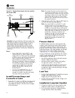
Page 20: ...s close to horizontal as possible see Do NOT use vertical ports for the excess flow valve 2 If required screw the 1 4 in 6 4 mm NPT pressure switch in the remaining threaded port N No ot te e Use Loct...

Page 21: ...fer to figures in Overview p 7 Pressure switch installed when selected refer to figures in Overview p 7 Purge discharge line connected to the downstream side piping to vent purge exhaust out the vent...

Page 22: ...at atmospheric pressure to assure proper operating conditions for the disk When the disk bursts the rapid pressure increase causes the excess flow valve to seal and the valve holder area becomes press...

Page 23: ...l valve spring spring hooks and valve plug O rings compatible with the specific refrigerant in use Valve body flange connections 3 in 76 2 mm valve 3 in 76 2 mm Trane flange 3 in 76 2 mm 150 ANSI flan...

Page 24: ...For more information please visit trane com or tranetechnologies com Trane has a policy of continuous product and product data improvements and reserves the right to change design and specifications w...

Reviews: